Arrow International, Inc.
8
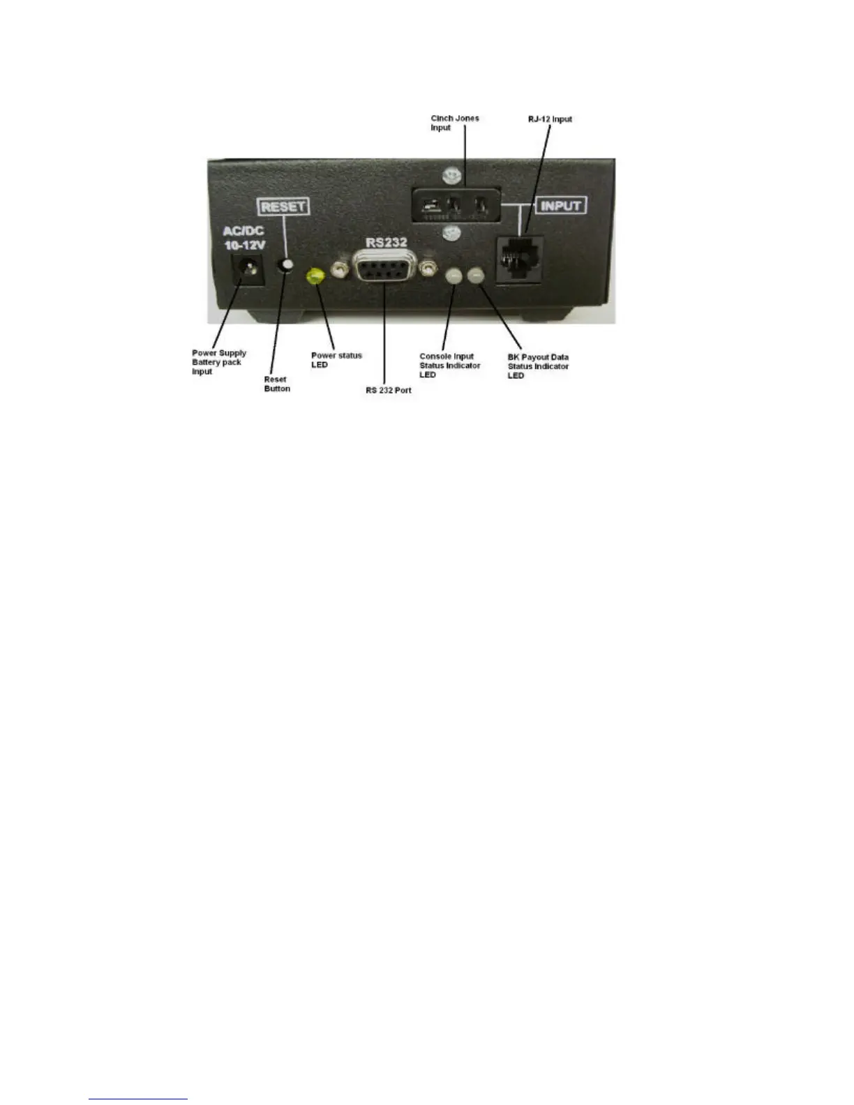
Figure 2.1
Figure 2.1 illustrates the input and status panel of the Arrow Bingo Converter. This panel
consists of the following:
Power Input------ Receptacle for the external power supply or the (optional) battery pack.
Reset Button---- Resets the Arrow Bingo Converter
Power Indicator LED----- Illuminates Yellow when proper voltage is applied to the unit.
RS 232 Interface---- Allows the Arrow bingo converter to communicate with a PC. (Optional)
Console Input Status LED---- Green = Good Signal, Red = No data. These indicators will blink
red and green when the unit is in flashboard test mode.
INPUT----- Console input. The input section consists of 1 RJ-12 and 1 Cinch Jones input. Only
one input can be used at any time.