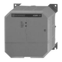
GENERAL OPERATING/WARRANTY MANUAL FOR CHILLER, FREEZER AND HEATED DISPLAY CABINETS
39
OPERATION SYSTEM PARAMETER SETTING
A. System parameter setting
1. Press [SET] key, the display flashes pattern “888”, then shows the symbol of the first system parameter “tS”, this means the controller entering the
parameter modifying phase, can press [▲] or [▼] key to choose other parameters(“td” or “di”) that is going to be adjust, Two keys [▲] or [▼] is used as
“scroll up and scroll down key”. During each parameter item in display, Press [SET] key, the display shows value of each parameter, can push [▲] or
[▼] key to modify setting value. Press the [SET] key, then modify the next parameter. Each choosing “tS”, “td”, “Sd”, “di”, “dd”, “tA” is available.
2. If there is no any key was pushed during thirty seconds, the controller jump into function of setting.
3. After power [ON] the compressor is delaying for protecting (power on delay “sd”). If you want to bypass the delay time and start immediately,
then you can push [▼] key display shows “Fon”. The controller then forces compressor to start up immediately.
4. When sensor shorted or broken, the display shows error code until system recover.
5. Press [Log] key, the displays flashes “dEf”, the controller go into defrost immediately.
LOCK SYSTEM PARAMETER SETTING
1. Press [SET] key for three seconds, the display begins flashing pattern “888”. While flashing, press both [▲] or [▼] keys
together until display shows “LO” (which means into parameters lock). Press [SET] again, the modified value would be showed. At this time, press
[▲] or [▼] to lock by choosing “y” or to unlock by choosing “n”.
2. After select system parameters to unlock push [SET] key, the display shows pattern “tH” can press [▲] or [▼] key to move to the next
parameter. Press [SET] key, the display flashes pattern set value, can press [▲] or [▼] key to increase or decrease the value by one unit, push the
[SET] key, the controller goes to modify the next parameter, finally; that the setting procedure is finished.
FUNCTION KEYS LED INDICATORS
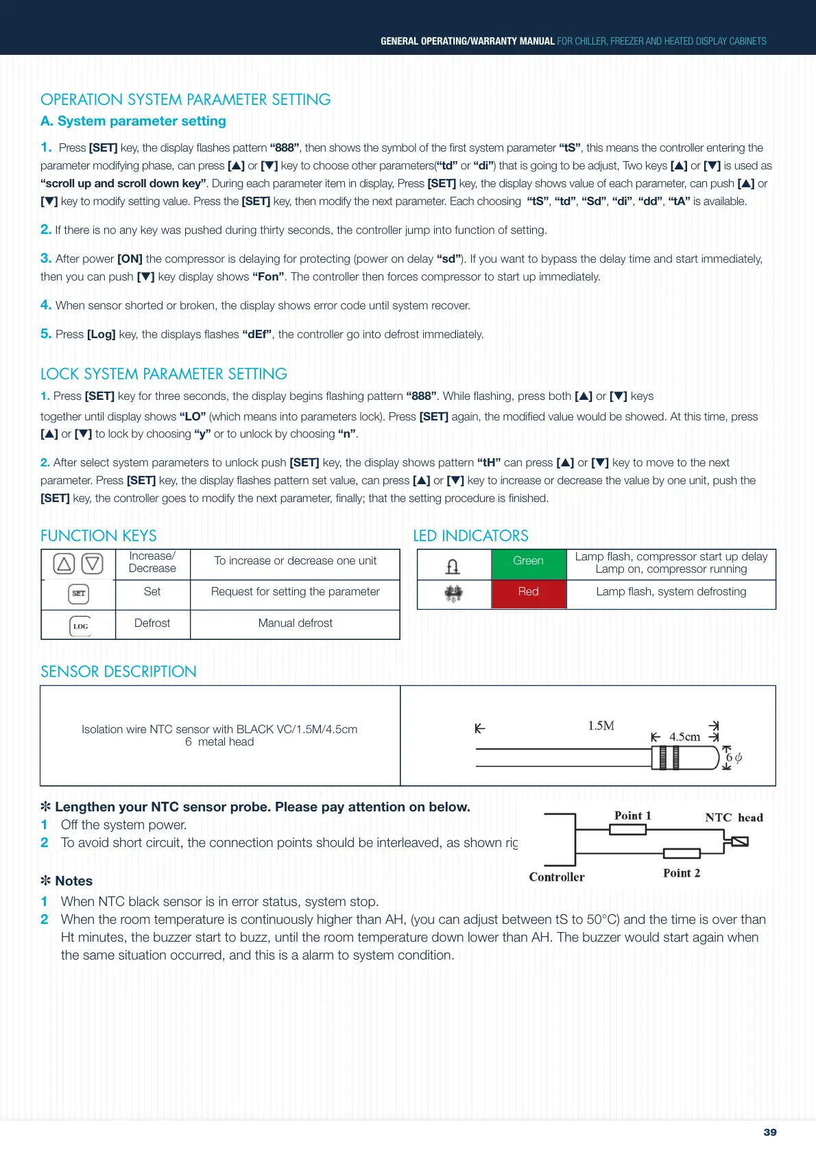
SENSOR DESCRIPTION
✽
Lengthen your NTC sensor probe. Please pay attention on below.
1 Off the system power.
2 To avoid short circuit, the connection points should be interleaved, as shown right.
✽ Notes
1 When NTC black sensor is in error status, system stop.
2 When the room temperature is continuously higher than AH, (you can adjust between tS to 50°C) and the time is over than
Ht minutes, the buzzer start to buzz, until the room temperature down lower than AH. The buzzer would start again when
the same situation occurred, and this is a alarm to system condition.
Green
Increase/
Decrease
RedSet
Defrost
To increase or decrease one unit
Request for setting the parameter
Manual defrost
Lamp flash, compressor start up delay
Lamp on, compressor running
Lamp flash, system defrosting
Isolation wire NTC sensor with BLACK VC/1.5M/4.5cm
6 metal head
 Loading...