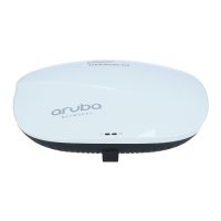
RAP-2WG Wireless Remote Access Point
Installation Guide
About the RAP-2WG
The Aruba RAP-2WG is part of a comprehensive wireless network solution. This
device works in conjunction with other Aruba products, such as Aruba Mobility
Controllers, and provides the following capabilities:
z Remote Access Point (RAP)
z Protocol-independent networking functionality
z IEEE 802.11 b/g operation as a wireless Access Point
z Central management, configuration, and upgrade through an Aruba Mobility
Controller
z Wireless Transceiver
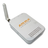
RAP-2WG Overview
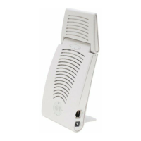
Rear View
Figure 1 Rear View
10/100Base-T Ethernet Ports
The RAP-2WG has two 10/100Base-T (RJ-45) Ethernet ports for wired network
connectivity.
z E0: Uplink port
z E1: LAN port
DC IN (Power Socket)
The RAP-2WG power adapter (included) connects to the DC IN port. The RAP-
2WG does not have an On/Off switch. The device turns on when the power
adapter is attached and plugged into a power outlet. The device turns off when
you disconnect the power adapter from the power source (outlet).
Antenna
The antenna allows client devices to connect to the RAP-2WG wirelessly.
Top View
Figure 2 Top View
LEDs
The RAP-2WG has five LED indicators that display the status of the device.
z WLAN: Indicates wireless status and activity.
z E1:Indicates activity and/or status on this port.
z E0: Indicates activity and/or status on this port
z POWER: When lit, the RAP-2WG is powered on.
z Status: Reports the RAP-2WG’s current status.
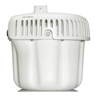
Bottom View
Figure 3 Bottom View
Reset Button
To reset the RAP-2WG, insert a small, narrow object, such as a pin or paperclip,
into the hole indicated in Figure 3 and press the button for 5 seconds, while
powering on the RAP-2WG. This returns the RAP-2WG to factory defaults.
Wall Mount Slots
The wall mount slots illustrated in Figure 3 accommodate mounting the RAP-
2WG on the wall or other vertical surfaces. Mounting hardware is not included.
RAP-2WG Installation
Tabletop Mounting
The RAP-2WG is equipped with four rubber feet designed to support the device
on a flat surface without damaging it. Install the RAP-2WG on a flat level surface.
Wall Mounting
The wall mount slots, on the back of the RAP-2WG, accommodate wall mounting
or mounting to other vertical surfaces.
1. Install two screws in the wall or vertical surface. If attaching the device to
drywall, Aruba recommends using appropriate wall anchors (not included).
2. Align the AP mounting slots to capture the surface screws (see Figure 4).
Figure 4 Built-in Wall Mount Slots
Connecting the Required Cables
The RAP-2WG must be connected to a network device that has access to the
Internet, such as a router or modem. To complete the installation of the RAP-
2WG:
1. Connect one end of the provided RJ-45 cable to port E0 on the RAP-2WG.
2. Connect the other end of the RJ-45 cable to a free RJ-45 port on your modem
or router.
3. Attach the provided power adapter to the DC IN port on the RAP-2WG.
4. Connect the other end of the power adapter to a power outlet.
The RAP-2WG is now powered on. To verify this, ensure that the PWR LED is
solid green.
Verifying Successful Installation
Once the RAP-2WG’s PWR LED has come up, the device will take 2 to 3 minutes
to complete the boot cycle. Once the boot cycle is complete, you can connect to
your company or corporate network.
Provisioning at Home
If your IT administrator instructed you to provision your RAP-2WG, complete
the following steps after the RAP-2WG has been powered.
1. Connect one end of a second RJ-45 cable to port E1 on the RAP-2WG and the
other end to your computer.
2. Open a web browser and navigate to any URL.
3. An Aruba web page will appear (see Figure 5), requesting the IP address of
the master controller. Enter the IP address provided to you by your IT
administrator.
The RAP-2WG will connect to the designated master controller and download
the necessary provisioning information. When the RAP-2WG comes back up,
it is ready to use.
Figure 5 Manual Provisioning Page
When the RAP-2WG has been successfully provisioned, a screen (Figure 6)
appears. This screen displays network information pertaining to the
connection between the RAP-2WG and its controller.
Figure 6 Provisioning Successful
It takes approximately 5 minutes provisioning process to be completed.
4. Once completed successfully, disconnect the RJ-45 cable from your
computer and the E1 port on the RAP-2WG.
5. Restart your browser.
If your RAP-2WG does not provision successfully, the screen indicates where the
failure occurred, as shown in Figure 7. If this (or a similar) screen appears,
contact your IT administrator.
Figure 7 Unable to Complete Provisioning Process
Local Debugging
The RAP-2WG includes built-in local debugging capabilities that allow you to
report information about the RAP-2WG to your IT administrator. To access this
tool, please contact your IT administrator.
Troubleshooting
If your computer is to obtain an IP from the RAP-2WG, try the following trouble
shooting steps. If the procedure is not successful, contact your IT administrator.
1. Unplug the Power and Ethernet cables.
2. Reset the RAP-2WG to its factory default setting by holding down the reset
button (use a pin or paperclip to hold down the button).
3. Power on the RAP-2WG (plug-in the power cord) while still holding down the
reset button.
4. Wait for the status LED to start blinking (about 5 seconds) then release the
reset button.
5. Plug-in your WAN connection to port 0.
6. Connect your laptop to port 1 using the RJ-45 cable.
Package Contents
z 1 x RAP-2WG Remote Access Point
z 1 x Installation Guide (this document)
z 1 x RJ-45 Ethernet Cable
z 1 x Power Adapter
Inform your supplier if there are any incorrect, missing, or damaged parts. If possible,
retain the carton, including the original packing materials. Use them to repack the
product in case there is a need to return it.
Before You Begin
Before installing your RAP-2WG Remote Wireless Access Point, please ensure
you have the following:
z 1 x RJ-45 Ethernet Cable (included)
z 1 x Power Adapter (included)
z RAP-2WG (included)
z 1x Additional RJ-45 Cable (require for Provisioning at Home, not included)