2Aruba 200 Series Access Points | Installation Guide
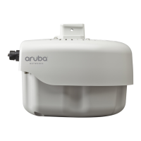
External Antenna Connectors
The AP-204 is equipped with two external antenna connectors. The connectors are labeled ANT0 and ANT1, and correspond to
radio chains 0 and 1. (see Figure 2).
Table 1 AP-200 Series Series LED Meanings
LED Color/State Meaning
PWR Off No power to AP
Red Error condition
Green - Flashing AP booting
Green - Steady AP ready
ENET Off Ethernet link unavailable
Yellow - Steady 10/100Mbps Ethernet link established
Green - Steady 1000Mbps Ethernet link established
Flashing Ethernet link activity
5 GHz Off 5 GHz radio disabled
Yellow - Steady 5 GHz radio enabled in non-HT WLAN mode
Green - Steady 5 GHz radio enabled in HT WLAN mode
Flashing - Green 5 GHz Air or Spectrum Monitor
2.4 GHz Off 2.4 GHz radio disabled
Yellow - Steady 2.4 GHz radio enabled in non-HT WLAN mode
Green - Steady 2.4 GHz radio enabled in HT WLAN mode
Flashing - Green 2.4 GHz Air or Spectrum Monitor
 Loading...