Do you have a question about the Aruba AP-203RP and is the answer not in the manual?
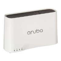
| Model | AP-203RP |
|---|---|
| Type | Wireless Access Point |
| Wireless Standard | 802.11ac |
| Maximum Data Rate (5 GHz) | 867 Mbps |
| Maximum Data Rate (2.4 GHz) | 300 Mbps |
| PoE | 802.3af PoE |
| Frequency Band | Dual-band |
| MIMO | 2x2 |
| Antenna | Integrated |
| Ethernet Ports | 1 x 10/100/1000 |
| Operating Temperature | 0°C to 40°C |
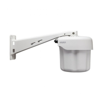
| Mounting Options | Wall, Ceiling |
Indicates the operating condition of the access point through color and state.
Shows the operating mode of the access point's wireless radios.
Indicates activity transmitted to/from the wired ports.
Indicates when the access point provides Power over Ethernet to a connected device.
Details the three active Ethernet ports (E0-E2) and their capabilities.
Guidance on choosing optimal locations considering RF plans and interference sources.