Aruba 340 Series Access Points |Installation Guide 3
Table 2 Radio Status LEDs
LED Display Settings
The LEDs have three operating modes that can be selected in the system management software:
z Default mode: Refer to Table 1-4
z Off mode: LEDs are off
z Blink mode: LEDs blink green
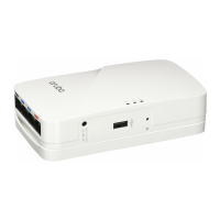
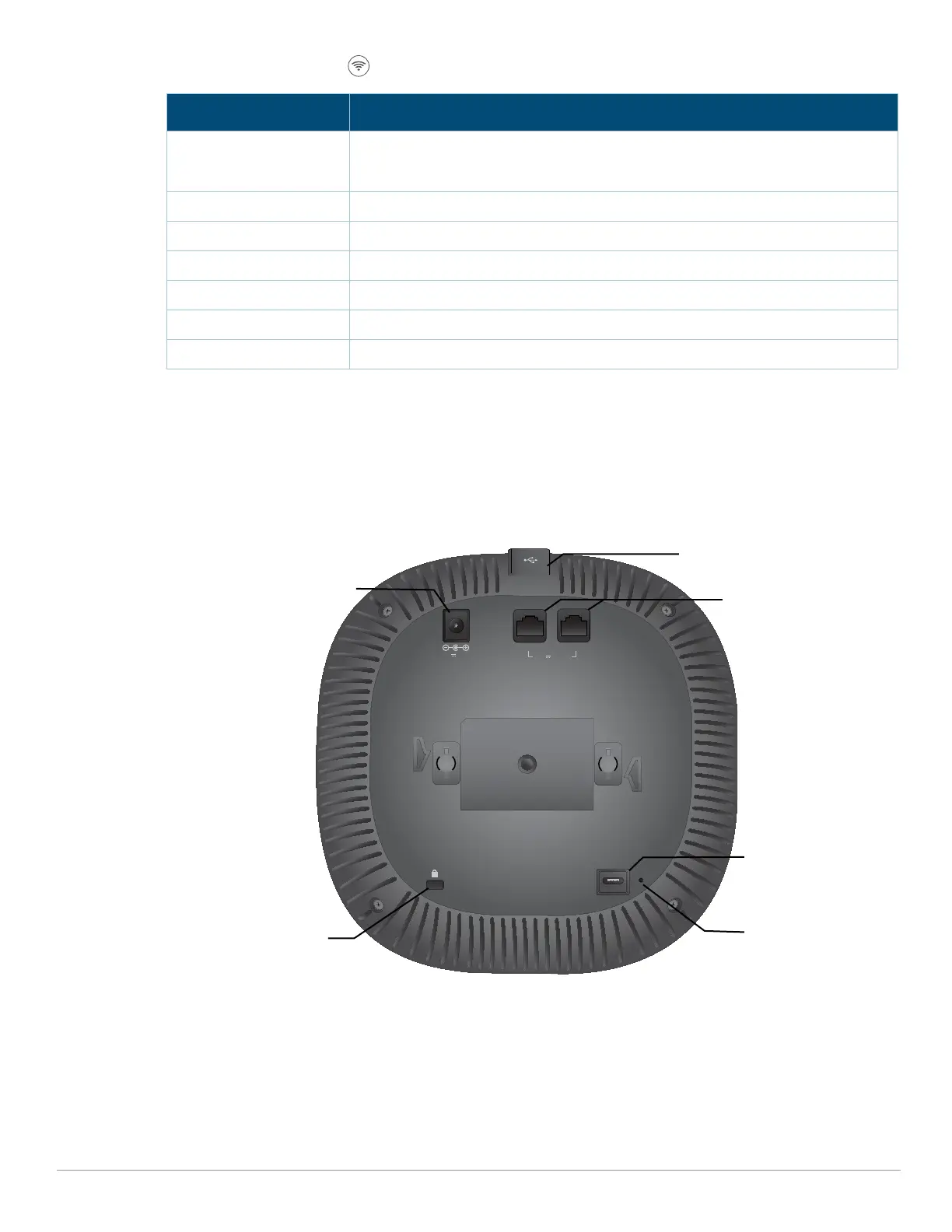
Figure 2 AP-344 access point (rear view)
External Antenna Connectors
The AP-345 access points are equipped with four external antenna connectors located on the front
corners of the access point (see Figure 3).
Color/State Meaning
Off Meets one of the following conditions:
z device is powered off
z both radios are disabled
Green- solid Both radios operating in access mode
Green- blinking
1
One radio operating in access mode; one radio disabled
Amber- solid Both radios operating in monitor mode
Amber- blinking One radio operating in monitor mode; one radio disabled
Green/Amber- alternating One radio operating in access mode; one radio in monitor mode
Blue- On Radios operating in dual-5GHz mode
CONSOLE
48V 650mA
K
ENET1 ENET0
57V 600mA
USB port
DC power socket
Ethernet ports
Reset button
Kensington Lock
Console port
 Loading...