Aruba 530 Series Campus Access Points | Installation Guide 3
Table 2 Radio Status LEDs
1 Alternating: one second each color, 2 second cycle.
LED Display Settings
The LEDs have three operating modes that can be selected in the system management software:
Default mode: Refer to Table 1 and Table 2
Off mode: LEDs are off
Blink mode: LEDs blink green
Force the LEDs into off mode and back to software defined mode by pressing the reset button for a short
duration. Warning: pressing the reset button for longer than 10 seconds may cause the AP to reset and return to
factory default state.
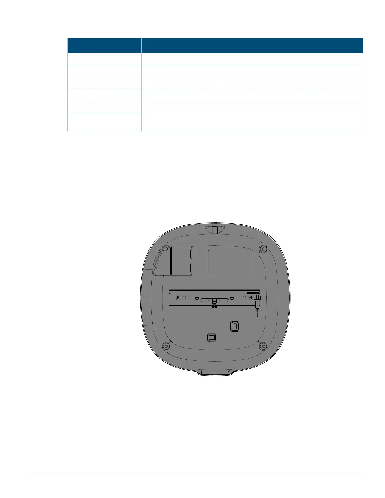
Figure 3 AP-535 access point (rear view)
External Antenna Connectors
The AP-534 access points are equipped with four external antenna connectors located on the front
corners of the access point (see Figure 4).
Color/State Meaning
Off AP powered off, or both radios disabled
Green- solid Both radios enabled in access mode
Green- blinking One radio enabled in access mode, other disabled
Amber- solid Both radios enabled in monitor mode
Amber- blinking One radio enabled in monitor mode, other disabled
Green/Amber-
alternating
1
Green: one radio in access mode
Amber: one radio in monitor mode