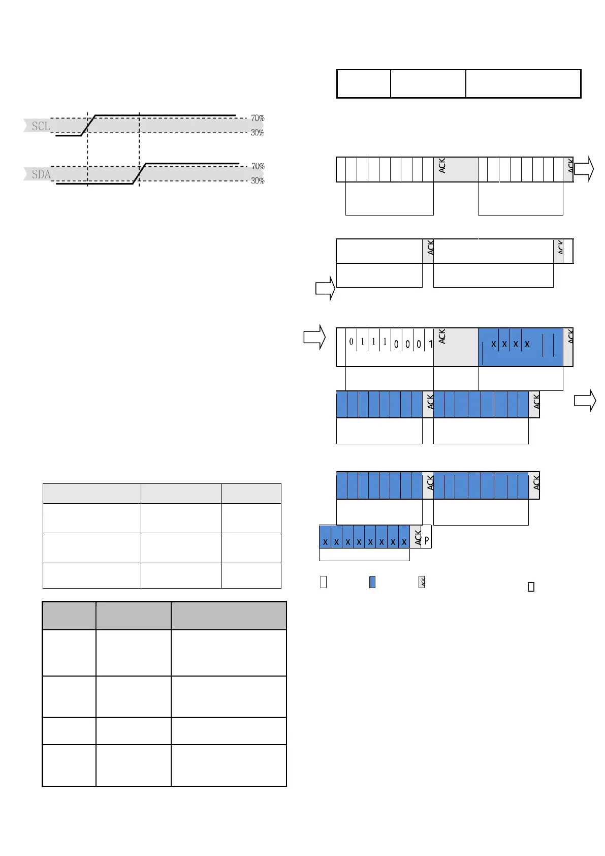
Figure 13 Start Transfer Status ( S ) - When SCL is high, SDA transitions from high
to low. The start state is a special bus state controlled by the host, indicating the
start of the slave transfer ( after the Start , the BUS bus is generally considered
to be busy)
Figure 14 Stop Transfer Status ( P ) - When SCL is high, the SDA line transitions
from low to high. The stop state is a special bus state controlled by the master
that indicates the end of the slave transfer ( after the Stop , the BUS bus is
generally considered to be idle).
5.3 send command
After the transmission is initiated, the subsequently
transmitted I 2 C first byte includes the 7 -bit I 2 C
device address 0x38 and one SDA direction (read R :
'1' , write W : '0' ). After the first falling edge of the
SCL clock 8, by pulling the SDA pin (ACK bit),
indicating proper reception of the sensor. After
issuing the initialization command ( '1110'0001'
represents initialization, '1010'1100' stands for
temperature and humidity measurement), the MCU
must wait for the measurement to be completed. The
basic commands are summarized in Table 9 . Table 10
shows the status bit descriptions returned by the
slave.
Table 10 status bit description
Trigger measurement data
ACK
S Start P Stop
Note: The sensor takes time to collect . After the host sends a
measurement command ( 0xAC ) , the delay is over 75ms and the
converted data is read and the returned status bit is normal. If the
status bit [Bit7 of] is 0 for the data can be read normally, the sensor 1
is the busy state, the host needs to wait for the data processing is
completed.
5.4 Soft reset
This command (see Table 9 ) is used to restart the
sensor system without turning the power off and on
again. After receiving this command, the sensor
system begins to reinitialize and restores the default
settings. The soft reset takes less than 20ms
 Loading...