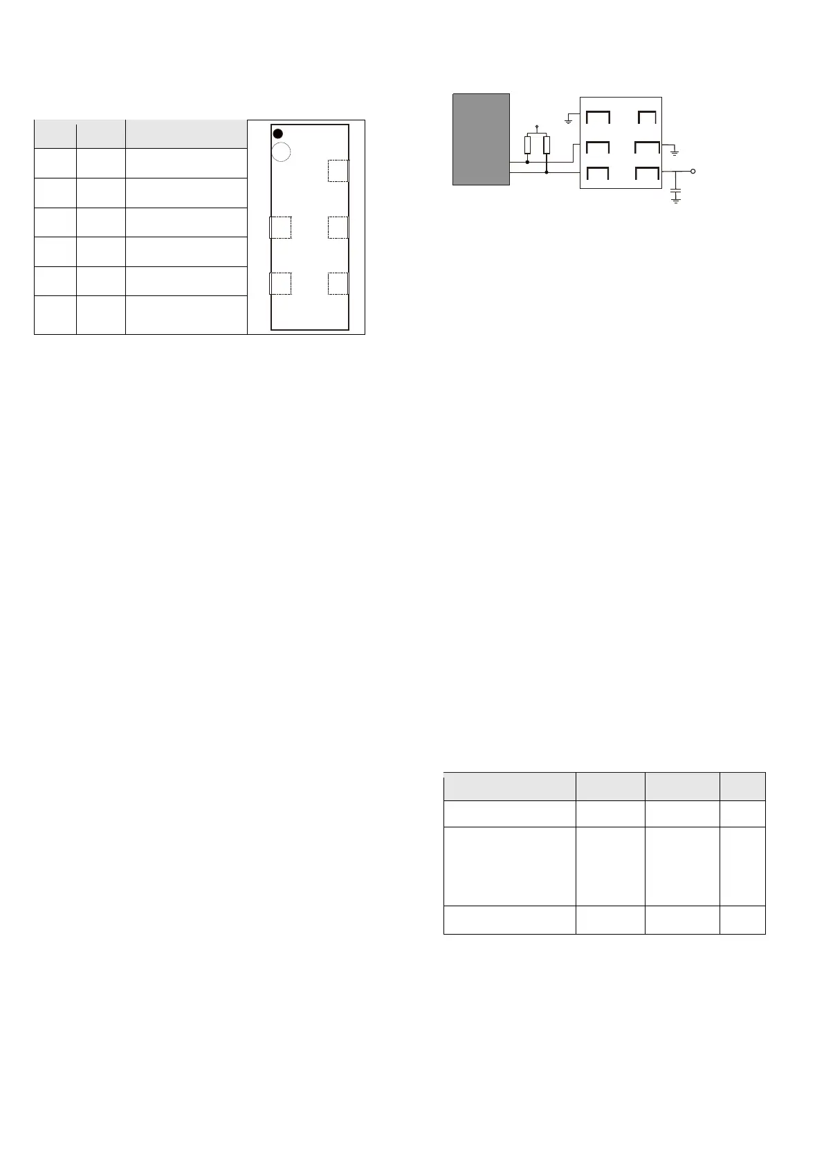
Table 5 AHT10 pin distribution (top view).
3.1 Power supply pin (VDD, GND)
AHT10 power supply range of 1.8-3.6V,
recommended voltage is 3.3V. A 100nF decoupling
capacitor must be connected between the power
supply ( VDD ) and ground ( GND ) and the
capacitor should be placed as close as possible to
the sensor - see Figure 11 .
3 . 2 Serial clock SCL
SCL is used for communication synchronization
between the microprocessor and the AHT10 . Since
the interface contains completely static logic, there
is no minimum SCL frequency.
3.3 serial data SDA
The SDA pin is used for data input and output of
the sensor. SDA is active on the rising edge of the
serial clock ( SCL ) when a command is sent to the
sensor , and SDA must remain stable when SCL is
high . After the falling edge of SCL , the SDA value
can be changed. To ensure communication
security, the effective time of the SDA should be
extended to TSU and THO before and after the
rising edge of SCL - see Figure 12 . When reading
data from the sensor, SDA is low after SCL active
(TV), and maintained until the falling edge of SCL.
Figure 11 shows a typical application circuit that includes a pull-up resistor RP
and a decoupling capacitor between VDD and GND。
Note : 1. The power supply voltage of the host MCU must be consistent with
the sensor when the product is in use .
2, To further improve the reliability of the system, the sensor power can be
controlled.
3, Only a single AHT10 can be connected to the I 2 C bus and no other I 2 C
devices can be connected .
To avoid signal collisions, the microprocessor ( MCU )
must only drive SDA and SCL low. An external pull-up
resistor (eg 10k Ω ) is required to pull the signal high.
Pull-up resistors are usually already included in the
microprocessor In the I/O circuit. Reference table 7
and table 8 can get detailed information about sensor
input / output characteristics.
4 Electrical characteristics
4.1 Absolute maximum rating
The electrical characteristics of AHT10 are defined in
Table 1 . The absolute maximum ratings given in
Table 6 are stress ratings only and provide more
information. Under such conditions, it is not
advisable for the device to perform functional
operations. Prolonged exposure to absolute
maximum ratings may affect sensor reliability.
 Loading...