Sensor performance
Relative humidity
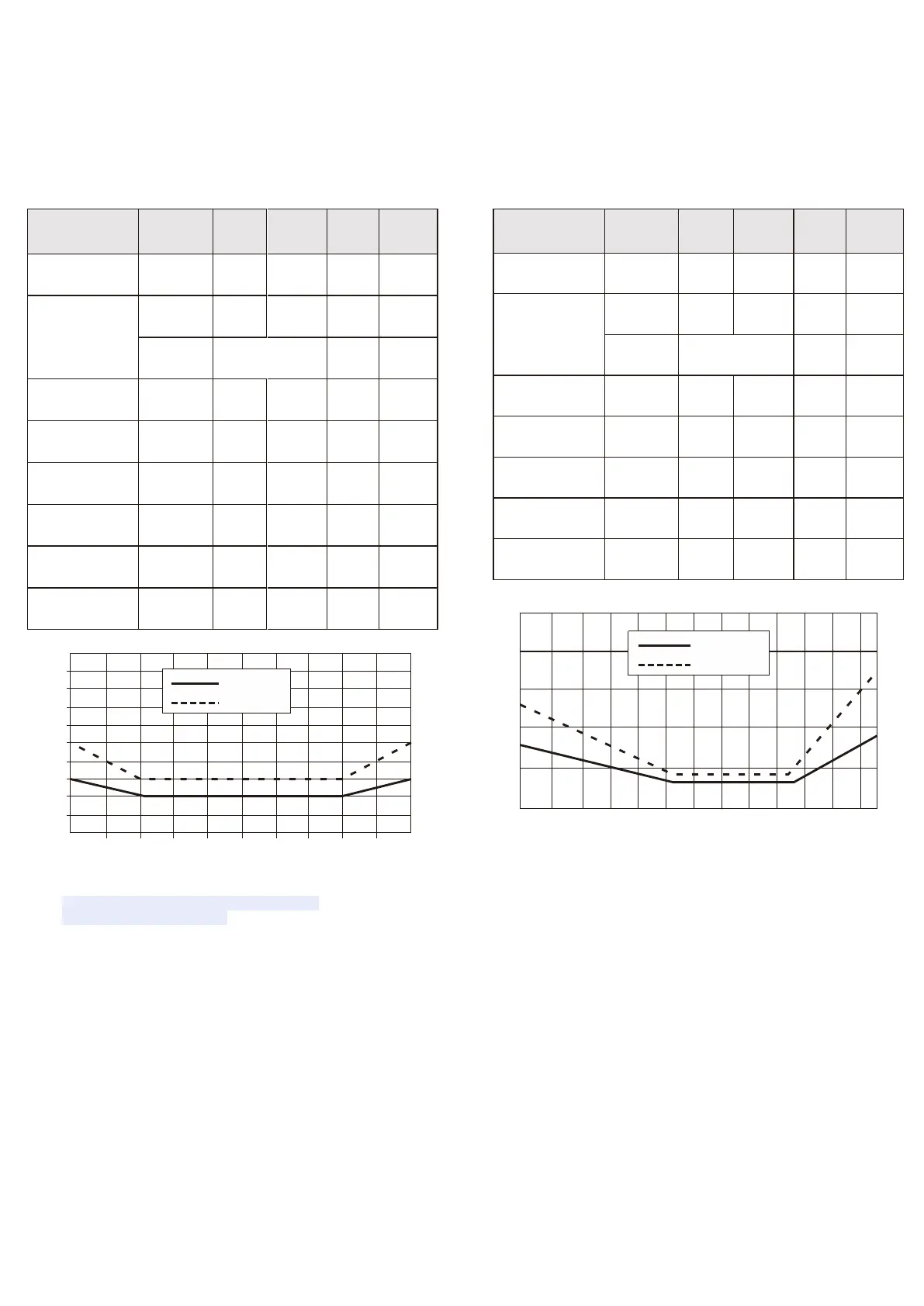
table 1 humidity characteristics table △RH(%RH)
0 10 20 30 40 50 60 70 80 90 100
Figure 2 The maximum error of relative humidity at 25 °C
1. This accuracy is the test accuracy of the sensor at a
factory voltage of 3.3V at 25 °C . This value does not
include hysteresis and nonlinearity and only applies
to Non-condensing conditions.
2 The
time required to
achieve a first-order response of 63% at 25 ° C and 1 m /
s airflow.
2. Normal operating range: 0-80% RH, beyond this range,
sensor readings will be biased (drift <3%
RH after 200 hours at 90% RH humidity ) . The scope of
work is further limited to -40– 80 °C .
3. If there are volatile solvents, irritating tapes, adhesives,
and packaging materials around the sensor, the
readings may be high. Please refer to the relevant
documents for detailed instructions.
4. The minimum and maximum values of supply current and power are based
on VDD = 3.3V and T < 60 ° C conditions. The average is the value measured
once every two seconds.
Temperature
table 3 temperature characteristics table
-40 -20 0 20 40 60 80
Figure 3 Typical temperature error and maximum error
5. The response time depends on the thermal conductivity of the sensor
substrate.
6. Contact surface means The metal layer on the PCB where the SMD pads
are soldered.
7. Solder mask The top layer of the PCB covers the insulating layer on the
connecting line.
8. The type of solder is related to the size of the internal particles of the
solder. Type 3 sizes range from 25 – 45 μm powder.
9. 75% RH can be easily saturated NaCl is generated.
 Loading...