6 7
514362-001514362-001
1
2
DC
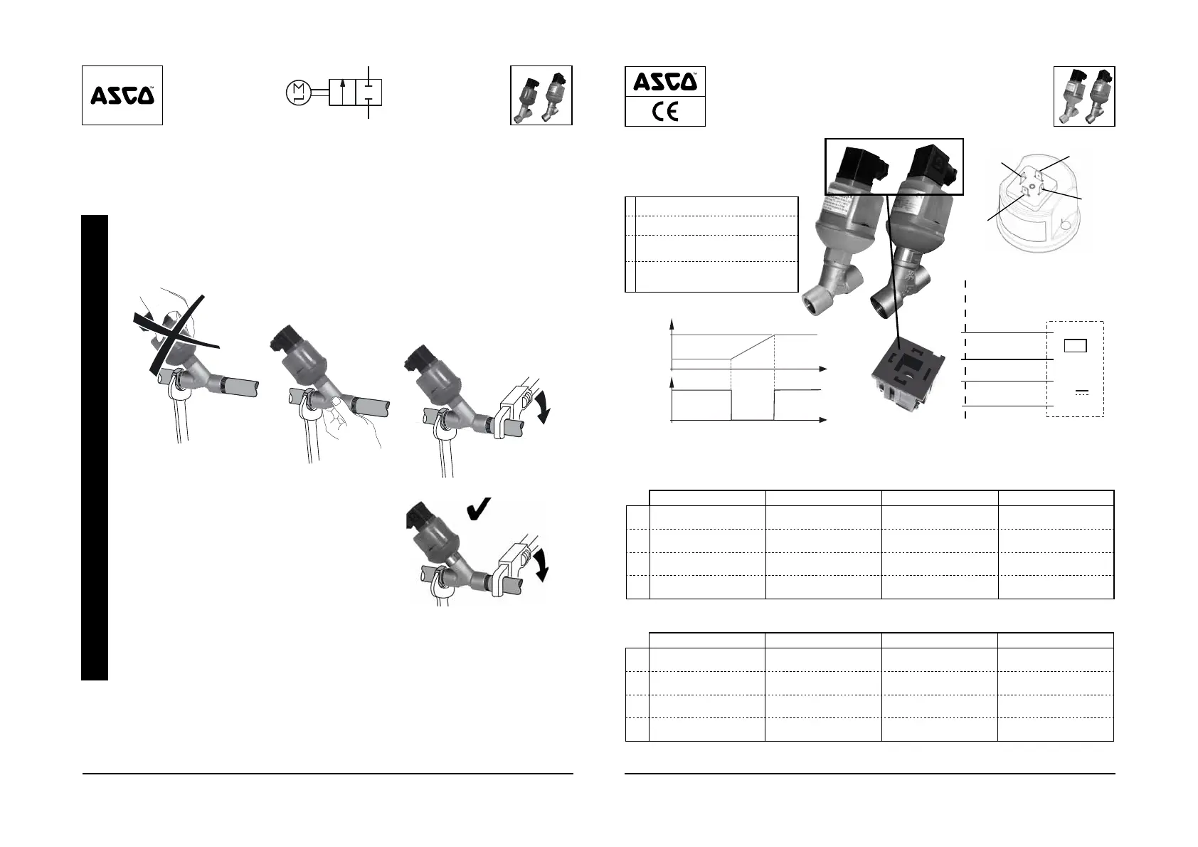
✓
✓
MOUNTING «K» + «X»
«X»
«K»
FR DE ES IT
(I)
entrée Eingang entrada input
(II)
signal de retour Stellungsrückmeldung Retorno de estado ritorno
(IV)
sortie Ausgang salida output
(V)
alimentation électrique Spannungsversorgung Alimentación eléctrica Alimentazione elettrica
4
3
1
2
0V
24V
Output (IV)
PLC
Input (I)
state return (II)
power supply (V)
1
2
3
4
NL PT RU KZ
(I)
input entrada
вход кіріс
(II)
terugkeer naar stand retorno de estado
возврат состояния күйді қайтару
(IV)
output saída
выход шығыс
(V)
voeding alimentação elétrica
источник питания қуат көзі
24 V
±10 %
DC
(NBR / PBT «K» / FPM / 316L «X»)
1
24 V / DC
2
0 V
3
setpoint (0-10 V or 4-20 mA)
4
feedback signal
[24 V switch]
t
Setpoin
24V
0V
Valve
position
position «a»
position «b»
state return (II)
1
2
3
4
DC

 Loading...