3834887
2
3834887
3
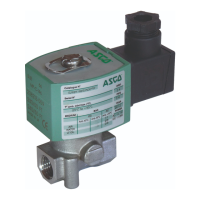
DESCRIPTION (Figs. 1 and 2)
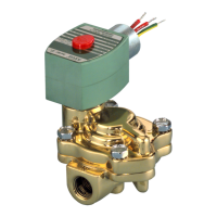
The valves are equipped with a piston-type operator of 50, 63, 90
or 125 mm in diameter. Series 290 normally closed 2/2 valves are
equipped with a profi led disc. Series 390 normally closed 3/2 valves
are equipped with a standard disc.
A Positioner
D
positioning unit, including a linear potentimeter, a pro-
cessor and two pilot valves, is standard fi tted on the valves.
- Single loop control
-
Double loop control for positioner with directly connected external sensor.
APC software for modifi cation of control parameters is available for download
at: www.asconumatics.eu. The APC software is required for double loop control.
The proportional valve is factory-adjusted. The Positioner
D
is equipped
with an electronic “shut off” system to exhaust the pilot chamber at
0 setpoint to ensure that the valves are tight when closed.
1
2
A
Pp
21
0-10 V
4-20 mA
Fig. 1 Fig. 2
OPERATION (Figs. 1 and 2)
NC – Normally closed: The valve is closed when no pilot pressure
is supplied by the positioner to the actuator.
The valve opens when the positioner supplies a pilot pressure.
In the auto-adjust phase, adapt the pilot pressures according to
the actuator:
2 to 3 for an actuator with very low pilot pressure (1,5 b)
3 to 5 bar for an actuator with low pilot pressure (2,5 b)
5 to 7 bar for an actuator with high pilot pressure (4 b)
Fluid entry under the valve disc via port 2 (2/2) or 3 (3/2).
No fl uid entry above the disc.
On loss of power the valve returns to the fail close position or the
disc position is maintained.
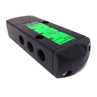
INSTALLATION AND PUTTING INTO SERVICE (Fig. 3)
The device is supplied factory installed and adjusted.
Operator diameters 63, 90 and 125 mm: Make sure the unused orifi ce
(Fig. 1, no. A) is not sealed with a plug. This orifi ce must remain open
to allow the pilot air to exhaust to atmospheric pressure.
The fi nal installation consists of connecting the electrical and pneumatic supply;
the device is then ready for operation in accordance with the setpoint values.
The green LED 3 lights up when power is ON.
The bottom LED 4 (orange) lights up when the valve is fully closed.
The top LED 1 (yellow) lights up when the valve is fully open.
A rapidly fl ashing red LED 2 indicates a device malfunction, see “Error
Defi nitions” on last page.
Description
ERROR No.
LED 1 LED 2 LED 3 LED 4
OPEN
ERROR
POWER
CLOSED
Hold position
Valve OPEN
Valve CLOSED
Valve moves to open
Valve moves to close
Description
ERROR No.
LED 1 LED 2 LED 3 LED 4
OPEN
ERROR
POWER
CLOSED
Positioner in initialisation mode
Positioner in manual mode
Setpoint > 20,5 mA / 10,25 V
1
Setpoint < 3,5 mA
2
Positioner not initialised
3
Component error
4
LED on
LED off
LED slow fl ashing
LED quick fl ashing
Fig. 3
ELECTRICAL CONNECTION (Fig. 4)
All electrical connections must be made by trained and qualifi ed personnel
only and be in accordance with your local regulations and standards.
1) Connection by cable and cable gland
CAUTION:
• Before starting any work, turn off the electrical current and
shut off the air supply to power off the components.
Unscrew and remove the cover.
Connect the terminal block (fi g 4, no. 1) as indicated below.
Supply voltage 24 V DC.
• Pin 1: +24 V DC supply
• Pin 2: GND supply
• Pin 3: Setpoint (0-10 V or 4-20 mA)
• Pin 4: GND setpoint
• Pin 5: External sensor input (double loop option)
• Pin 6: Disc position feedback
• Pin 7:
24 V ON/OFF output (disc position = setpoint)
Fig. 4
All screw terminals must be properly tightened prior to operation
(be sure to observe a tightening torque of 3 Nm).
The electrical connection is made by a cable gland M16 x 1,5 mm for
cable dia. 5-10 mm (be sure to observe a tightening torque of 3 Nm).
Put the cover and its seal back in place (be sure to observe a
tightening torque of 5 Nm).
General installation and maintenance instructions
Valves with Positioner
D
(2/2 and 3/2) - series 290-390
GB
3834887-A (A = R4)
Availability, design and specifi cations are subject to change without notice. All rights reserved.
General installation and maintenance instructions
Valves with Positioner
D
(2/2 and 3/2) - series 290-390
GB
2) Connection by M12 connector:
Pin
5
41
32
Single loop Double loop
1 + 24V
2 + Setpoint
3 GND
4 Disc position feedback External sensor input
5 ON/OFF output: 24 V PNP
Positioner
D
, single loop
terminal block
M12
5
41
32
1 + 24 V DC supply 1
2 GND supply 3
3 + Setpoint (0-10 V or 4-20 mA) 2
4 Setpoint GND 3
6 Disc position feedback 4
7
ON/OFF output: 24 V
PNP
5
Positioner
D
, double loop
terminal block
M12
5
41
32
1 + 24 V DC supply 1
2 GND supply 3
3 + Setpoint (0-10 V or 4-20 mA) 2
4 Setpoint GND 3
5 Exter
nal sensor input 4
7
ON/OFF output:
24 V
PNP
5
PUTTING INTO OPERATION
Valve installation: See I&M sheets for the series 290 2/2 valves and
series 390 3/2 valves (http://www.asconumatics.eu).
Positioner
D
unit characteristics:
- Pilot fl uid: Air or neutral gas, fi ltered at 50 m, without condensate,
lubricated or non-lubricated
- Supply pressure: 4 to 8 bar
- Ambient and pilot fl uid temperature: 0 to +50°C
- Electrical protection: IP66 (EN 60529)
Analog setpoints to be selected when ordering:
- Voltage setpoint 0 – 10 V (200 k input resistance)
- Current setpoint 4 - 20 mA (250 input impedance)
- Supply voltage: 24 V DC ±10%
- Power rating: max. 8,5 W
- Hysteresis: < 2% of max. disc stroke
- Accuracy: < 2% of max. disc stroke
- ON/OFF output: 24 V PNP /max. 500 mA
- External sensor signal (option) = setpoint signal (0-10 V or 4-20 mA)
- Disc position feedback signal = setpoint signal (0-10 V or 4-20 mA)
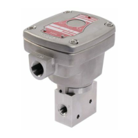
PNEUMATIC CONNECTION (Fig. 5)
Connection: G 1/8 at pressure inlet (no. 2).
Fig. 5
MANUAL OPENING AND CLOSING
It is possible to manually open and close the valve during normal operation.
Procedure:
1 – Remove the cover.
2 – To switch to manual mode, simultaneously press the “Open” button
(no. 3) and the “Close” button (no. 4) until the green LED fl ashes.
3 – Press the top button to open: The valve will open as long as the
button is pressed, it will stop opening as soon as the button is
released (fi g. 7).
Fig. 6 Fig. 7
Or,
Press the bottom button (no. 4) to close: The valve will close as
long as the button is pressed, it will stop closing as soon as the
button is released. (fi g. 7)
You can:
- Obtain information on the disc’s position with a voltmeter or an
amperemeter connected to pins 2 and 6.
Exit from the manual mode:
- To exit the manual mode, again simultaneously press buttons nos.
3 and 4 for 3 to 5 seconds; the disc will automatically be restored
into the setpoint position.
POSITIONER
D
UNIT REPLACEMENT
1- Removal of the unit to be replaced (fi g. 8)
a. Disconnect and remove all electrical and pneumatic supplies.
b. Disconnect the pneumatic connection to the valve and remove
connector no. 5 (not supplied in the kit).
c. Loosen screw F by several turns to remove the unit from its sup-
port.
d. Remove the unit + stem assembly and take care to protect the
stem against damage and bending stress.
e. Remove pneumatic supply connections nos. 5 and 6.
Fig. 8
Rep. 6
Rep. 5