5101 Engine Start Monitoring System
6 381333-474 C
System Components/Requirements
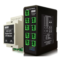
Generator Module (5101-GEN)
o Inputs
Requires power from 24Vdc (usually from generator battery)
Receives up to 8 individual signals from ATS modules (5101-ATS)
o Outputs
Sends engine start signal to the generator via form C output.
Provides alarm signal (form C) in case of fault.
Transfer Switch Module (5101-ATS)
o Inputs
TB1 is connected to the engine start signal relay of the transfer switch controls.
o Outputs
TB2 is connected to a generator module (5101-GEN)
Generator Module (5101-GEN) Requirements
The Generator module (5101-GEN) must be properly wired to the generator and transfer switch module (5101-ATS) for it
to operate correctly. The generator module requires 24Vdc control power. The module should be fed from the DC voltage
available at the generator.
Prior to operation, the DIP switches on the rear of the module must be configured for the applications. I.e. if the
application only requires 5 transfer switches, the other 3 available channels in the module should be disabled. By
disabling the unused channels, it prevents false alarms from starting the generator. Based on the system, the unit can be
used in 2 modes: START ON OPEN or START ON CLOSE. The user must determine which mode to use and program
the module accordingly using the S2-2 DIP switch. (See Settings for more information.)
The total length of connection wire between the generator module and the transfer switch module shall not exceed 1000 ft.
or 100 Ohms. The module is DIN rail mountable and should be used with standard 35mm DIN rail.
Transfer Switch Module (5101-ATS) Requirements
The Transfer Switch Module (5101-ATS) does not require any power to operate. The module must have its two terminal
blocks (TB1 and TB2) wired correctly. TB1 must be connected to the engine start signal relay of the transfer switch
controls. The TB2 should have 2 wires going to the generator module.
Like the generator module, the 5101-ATS is DIN rail mountable and should be used with standard 35mm DIN rail.