Page 3 of 4 I&M No. V_5993_R8
©
ASCO Valve, Inc.
50 Hanover Road, Florham Park, New Jersey 07932 www.ascovalve.com
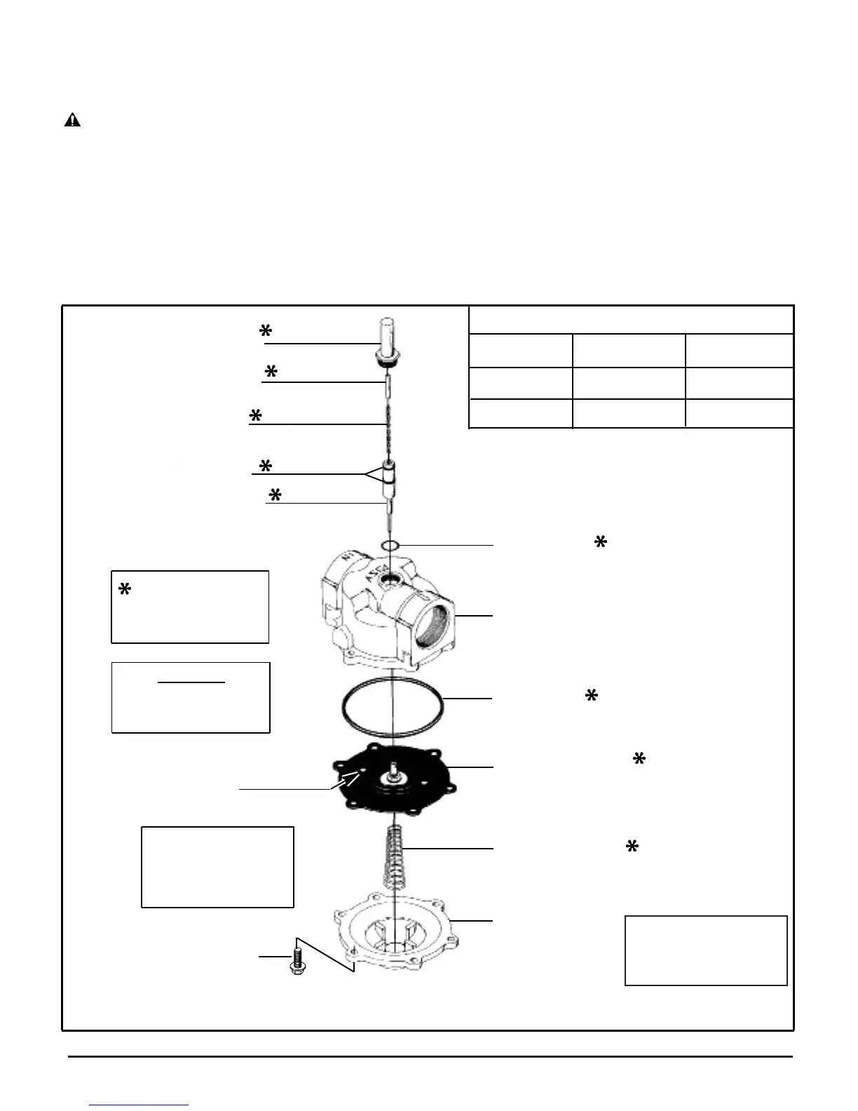
solenoid base
sub-assemb
ly
spring retainer
core spring
rider rings (2)
core assembly
CAUTION
Do not damage valve
seat in any manner
bleed hole
Locate bleed hole in
diaphragm assembly
approximately 30°
from valve outlet
bonnet screw
Part Name
Solenoid Base
Sub-Assembly
Bonnet Screws
Torque Chart
Torque Value
45±5 ft-lbs
100±10 in-lbs
bonnet gasket
valve body
body gaske
t
diaphragm assembly
diaphragm spring
(wide end to face
valve bonnet)
See Note1
valve bonnet
Figure 1. For Series 8215 AC and 8215G DC Constructions
(AC shown)
Torque Value
Newton-Meters
61±1 6,8
11,3±1,1
Indicates Parts
Supplied in ASCO
Rebuild Kit
13. Replace valve bonnet and bonnet screws, start all bonnet
screws by hand. Torque bonnet screws in a crisscross
manner to 100 ± 10 in-lbs (11,3, ± 1, 1Nm). If necessary,
make up piping and fi nal electrical hookup.
WARNING: To prevent the possibility of
death, serious injury or property damage,
check valve for proper operation before
returning to service. Also perform internal
seat and external leakage tests with a
nonhazardous, noncombustible fl uid.
14. Restore line pressure and electrical power supply to valve.
15. After maintenance is completed, operate the valve a few
times to be sure of proper operation. A metallic “click”
signifi es the solenoid is operating.
ORDERING INFORMATION
FOR ASCO REBUILD KITS
Parts marked with an asterisk (*) in the exploded view are
supplied in Rebuild Kits.
•When Ordering Rebuild Kits for ASCO valves, order the
Rebuild Kit number stamped on the valve
nameplate.
+ If the number of the Rebuild Kit is not visible order them
and specify your valve’s Catalog Number and Serial Number.
Note1: For 8215083,
the spring is
assembled in reverse
of what is shown.

 Loading...