Page 1 of 2
50-60 Hanover Road, Florham Park, New Jersey 07932
ASCO Valves
MCMXCIII All Rights Reserved.
Printed in U.S.A.
Installation & Maintenance Instructions
SERIES
Form No.V6855R1
3-WAY DIRECT-ACTING SOLENOID VALVES
8314
UNIVERSAL OPERATION Ċ 1/4 NPT Ċ 1/16 ORIFICE
BRASS OR STAINLESS STEEL CONSTRUCTION
AIR OR INERT GAS SERVICE
IMPORTANT: See separate solenoid installation and
maintenance instructions for information on: Wiring,
Solenoid Temperature, Causes of Improper Operation, Coil or
Solenoid Replacement.
DESCRIPTION
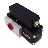
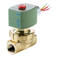
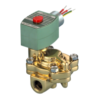
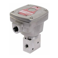
Series 8314 valves are 3-way direct-acting solenoid valves
designed for air or inert gas service. Valve bodies are made of
rugged brass or stainless steel. The valves may be provided with
a low power or intrinsically safe solenoid.
OPERATION
Universal (Pressure at any orifice)
Solenoid De-energized: Flow is from I to 3 or from 3 to I. Port
2 is closed.
Solenoid Energized: Flow is from I to 2 or from 2 to I. Port 3
is closed.
Flow Diagrams
Energized
De-Energized
INSTALLATION
Check nameplate for correct catalog number, pressure,
voltage, frequency, and service. Never apply incompatible
fluids or exceed pressure rating of the valve. Installation and
valve maintenance to be performed by qualified personnel.
Temperature Limitations
Fluid and ambient temperature range: -40F to +140F.
Future Service Considerations
Provision should be made for performing seat leakage, external
leakage, and operational tests on the valve with a
nonhazardous, noncombustible fluid after disassembly and
reassembly.
Positioning
Valve may be mounted in any position.
Mounting
Refer to Figure 1 for mounting brass valve with mounting
bracket or directly to valve body. Refer to Figure 2 for
mounting stainless steel valve with mounting bracket.
.147 [ 3.7 ] dia .31 [ 8 ]
deep for .164 [ 4.2 ] thread
cutting screw ( 2 holes
for mounting )
.88
.666
16.9
22
.58
15
.86
22
.68
17
.266 dia
6.8
.125 R, 4 places
3.2
Figure 1. Dimensions for direct mounting to valve body or
mounting bracket for brass valve construction.
.86
22
.68
17
.266 dia
6.8
.125 R, 8 places
3.2
.88
22
.59
15
Figure 2. Mounting bracket dimensions for stainless steel valve.
Piping
Connect piping or tubing to valve according to markings on
valve body. Refer to flow diagrams in OPERATION section.
CAUTION: To avoid damage or accidental
disengagement of cartridge assembly from valve body,
hold cartridge assembly securely by wrenching flats
when installing or removing piping at Port 3.
Apply pipe compound sparingly to male pipe threads only. If
applied to valve threads, the compound may enter the valve
ands cause operational difficulty. Avoid pipe strain by properly
supporting and aligning piping. When tightening the pipe ,do
not use valve or solenoid as a lever. Locate wrenches applied
to valve body or piping as close as possible to connection point.