IM14229-5
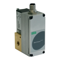
1) The valve must only be supplied with 24V DC ±10% and a max. ripple of 10% (no supply via diode bridge). Overvolt-
age or a ripple rate exceeding these tolerances can damage the electronics.
2) The max. current at the digital output is 200 mA/4.8W (PNP output). The output is protected against short circuit and
overload.
3) If a relay (inductive load) is connected to the pressure switch output, a freewheel diode or a varistor must be used.
4) A shielded cable must be used for protection against interference and EMC.
5) The valve body must be grounded with the earthing terminal PE (dia. M4)
2. ELECTRICAL CONNECTION
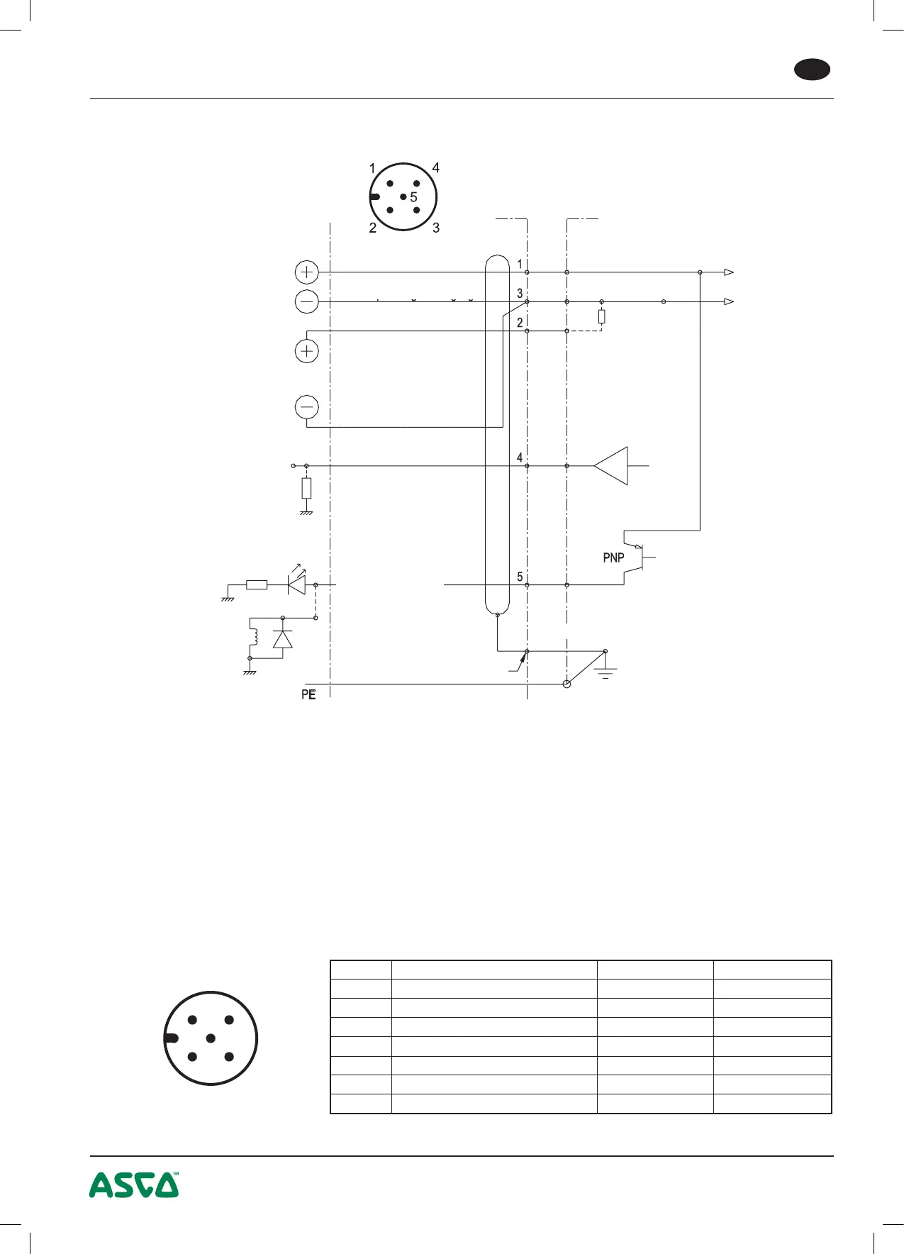
CONNECTOR PINNING / CABLE WIRING
5
5-pin M12 female connector
250 Ohm
at current
setpoint
Valve
M12 connector
+24V supply voltage
Supply voltage GND
Setpoint GND
(only for 6-wire cable)
Setpoint
0-10V
(or 0-20 / 4-20mA)
Feedback
0-10V
(or 0-20 / 4-20mA)
Control
Analog output:
Only at current output:
max. 500 ohm
PNP when setpoint is reached
(setpoint=feedback)
Shield
=200mA max./4.8W
Inductive
load
M4 connection
on valve body
Connector housing
Digital output:
❉ A 6-wire cable with separate analog ground is used for cable lengths over 2 m to set off the voltage
drop for the setpoint.
Pin Description 5-wire cable 6-wire cable
1 24V voltage supply brown brown
2 Analog setpoint input white white
3 Supply ground blue green
Analog ground ❉
yellow
4 Analog output (feedback) black pink
5 Digital output (pressure switch) grey grey
Body EMC screen shield shield
 Loading...