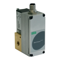
IM14229-9
Setpoint input : 0 ... 10 V (100 kOhm input resistance)
0 ... 20 mA / 4 ... 20 mA (250 Ohm input resistance)
Feedback output : 0 ... 10 V (max. 10 mA), short-circuit protected
0 ... 20 mA / 4 ... 20 mA (max. 24 VDC)
Digital output : pnp; open collector; max. 200 mA/4.8W, short-circuit protected
HIGH (24 VDC) if feedback=setpoint
LOW (open) if feedback≠setpoint
5.2 SPECIFICATIONS
Nominal
diameter
DN
(mm)
Supply
voltage
(1)
(stabilised)
Max. power
(W)
Max. current
(mA)
Insulation
class
Degree of
protection
Flow
(2)
Electrical connections
K
V
(Nm
3
/h)
at 6 bar
(l/min
ANR)
3
6
12
20
24 V=
+/-10%
12
24
34
44
500
1000
1400
1800
F IP 65
0,18
0,60
1,20
4,80
210
700
1400
5600
5-pin female M12 connector
or
7-pin female DIN connector
(1) Residual ripple: 10 %
(2) Test conditions according to ISO 8778: temperature: 20 °C, relative inlet pressure: 6 bar, relative outlet pressure: 5 bar
INSTALLATION AND OPERATING INSTRUCTIONS
1. Before putting into operation carefully check all electrical connections and the supply voltage (24 VDC ±10 %).
Overload can destroy the electronics. Recommended pre-fuse T2.0 A.
2. The electrical connection is made with a round connector M12x1. The connector must meet the requirements of
DIN 60079-15. The product was tested with connector catalogue no. 88100729.
In order to ensure conformity with ATEX Directive 2014/34/EU, the product must be installed in such a manner as
to protect the electrical connector from mechanical stress.
WARNING:
Do not disconnect the connector while under voltage!
When disconnected from power, use supplied protection cover to ensure IP protection.
3. Use shielded cables for the electrical connection of the valve. The shield, connector and control cabinet must be
EMC compliant. The valve body must be electrically connected to ground (PE, machine ground). Do not run con-
trol cables parallel to high-voltage lines, servo-motor control cables etc.
4. Min. wire cross-section of supply voltage cable: 0.50 mm
2
.
For longer cabling distances use larger cross-section cables as required.
5. Make sure that the valve is under pressure when a setpoint signal is applied to the valve (applying a setpoint signal
with no pressure on the valve will cause it to overheat).
6. The valve is factory adjusted.
7. The product must be returned to the factory for repair.

 Loading...