TD 92989EN
15 October 2014 / Ver. B
Installation Guide
IP-DECT Base Station & IP-DECT Gateway
24
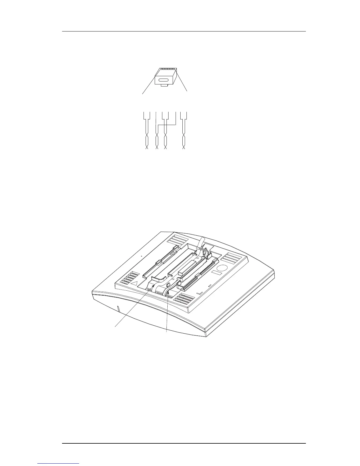
Pin the BS3x0/DB1 Cable
Figure 14. Connector pinning of the Data connector
IMPORTANT: If local power supply is used, the EPP cable pair must NOT be connected.
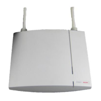
3.2.8 Connect the Base Station Cables
1 Only for IPBS1: If it is required that the cables enter the base station centrally from
above, guide the cables through the recess in the middle of the base station as
shown below.
2 Plug the modular jack of the data cable into one of the data/power connectors.
3 When an AC-adapter is used:
• Plug the modular jack of the AC-adapter in one of the data/power connectors.
• Plug the AC-adapter into a wall-outlet.
3.2.9 Mount the Base Station
Hold the base station flat against the mounting bracket and move it downwards until it
clicks, see below.