INSTALLATION GUIDE
Corridor Lamp 4 Terminating and Mounting the Room Bus RJ45 Connectors
8 Terminating and Mounting the Room Bus RJ45 Connectors
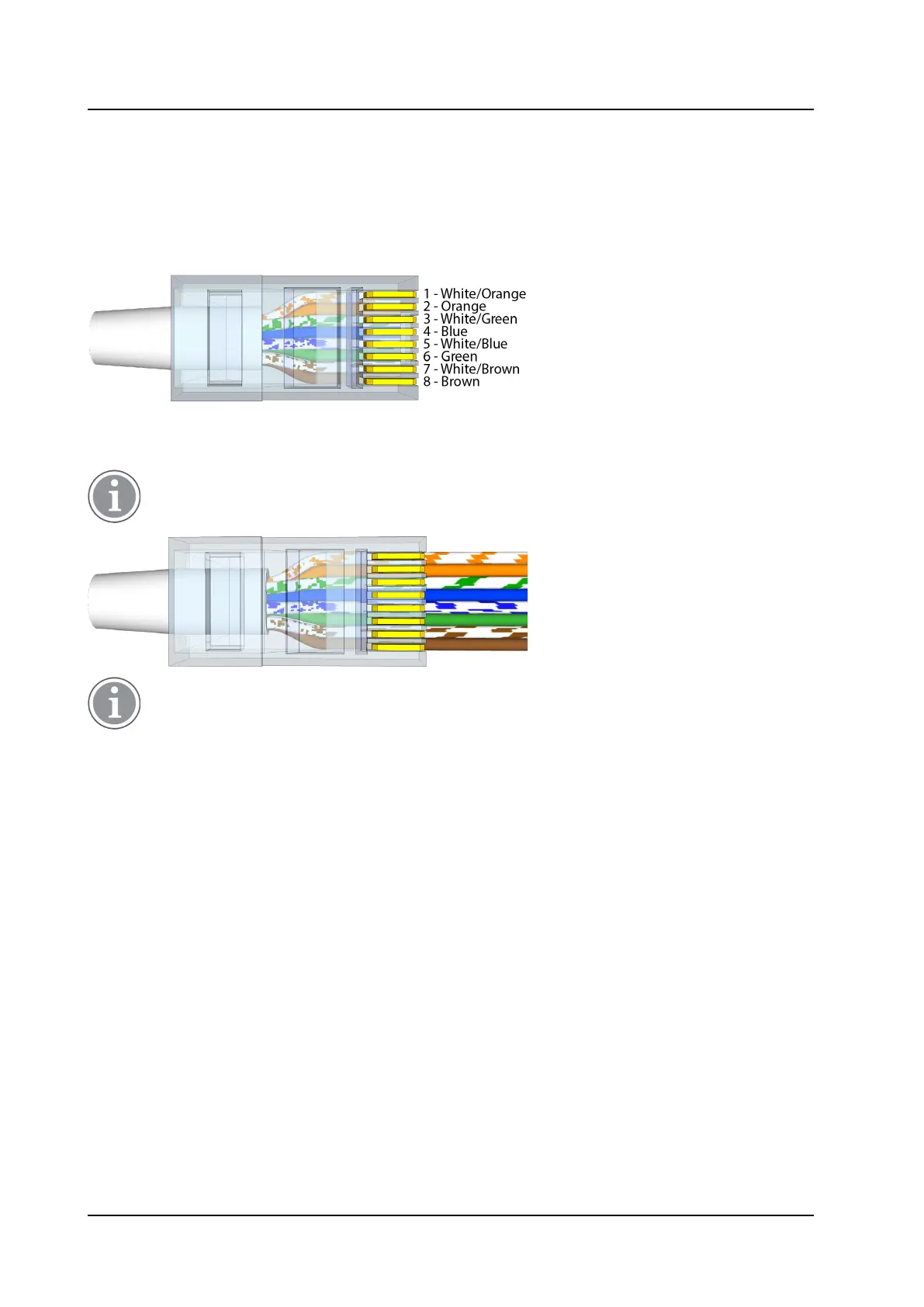
The NICL4 includes two active room bus RJ45 sockets. Crimp the RJ45 connector(s) to the room bus cable
(s) using the Ethernet T-568B termination color scheme. The following figure shows the correct pinout for
terminating the active room bus cables.
RJ45 connector for active room bus cable
For easy mounting of the RJ45 connector, use Easy RJ45 connectors that allow feeding excess wire length
through the connector. When crimping, the excess wire length will be cut automatically.
(Easy) RJ45 connectors are not included and must be ordered separately.
Easy RJ45 connectors require a dedicated crimping tool that includes a cutting mechanism to cut
the excess wire when crimping the connector on the cable.
To mount the RJ45 room bus connectors:
1. Ensure the active room bus cables are properly terminated with an RJ45 connector.
2. Plug the RJ45 connector into one of the RJ45 sockets on the NICL4 circuit board. When daisy chaining
the room bus from one peripheral device to the other, both RJ45 sockets will be used.
TD 93352EN / 25 January 2021 / Ver. A
11