Connections and DIP Switch Settings
INSTALLATION GUIDE
Corridor Lamp 4
6 Connections and DIP Switch Settings
Before attaching the PCB to its base, make all wire connections and DIP switch settings. Be sure that
required cables are properly connected. The following figures show the locations for each cable.
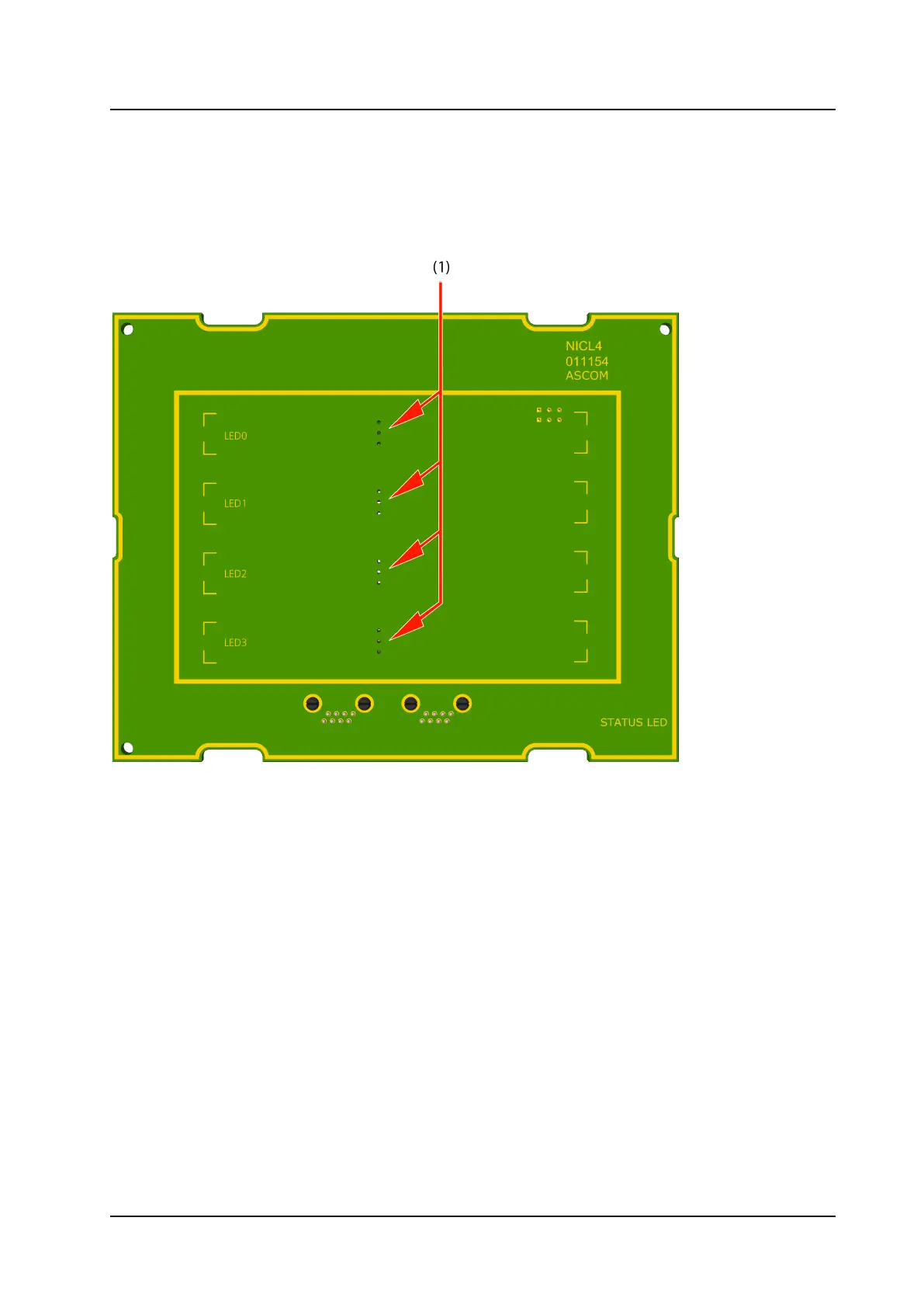
Figure 2. NICL4 Circuit Board - Front
Legend
(1) LED lamp (NILD2, NILD4–RGB) connections
8
TD 93352EN / 25 January 2021 / Ver. A