Setting the Corridor Lamp ID
INSTALLATION GUIDE
Corridor Lamp 4
7 Setting the Corridor Lamp ID
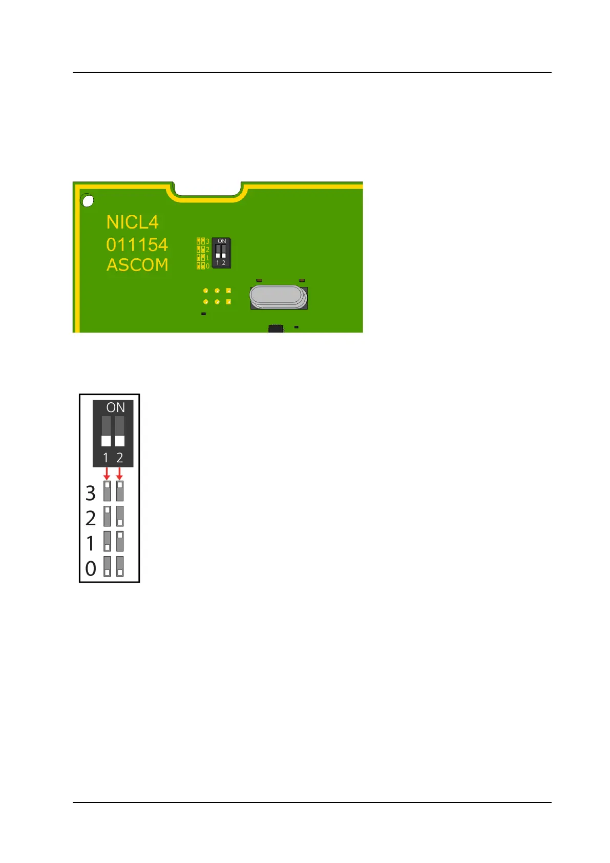
Before connecting any of the wires, first set the corridor lamp ID selection DIP switch. Up to four corridor
lamps (NICL4 only) can be connected to each room bus of the room controller (NIRC4 only). The following
figure illustrates the DIP switch found on the back of a NICL4 circuit board.
Figure 4. Corridor Lamp ID Selection DIP Switch
The following table shows the DIP switch settings for all IDs.
DIP switch settings for corridor lamp ID selection
To set a DIP switch:
1. Set the DIP switches to the ID (0 to 3) chosen for the NICL4. Use the ID table above to determine the
correct positions (ON or OFF) for the DIP switches.
2. Using a small screwdriver, gently slide the switch up for “ON” or slide it down for “OFF.”
10
TD 93352EN / 25 January 2021 / Ver. A