TD 90227GB
10 October 2013 / Ver. D
System Installation
Ascom Paging System
4
2 Transmitters
Note: Transmitter are only required when paging functions are to be used.
The Terminal transmitters are controlled by the Cen
tral Unit and receives pagings in
transmit format on the D-bus.
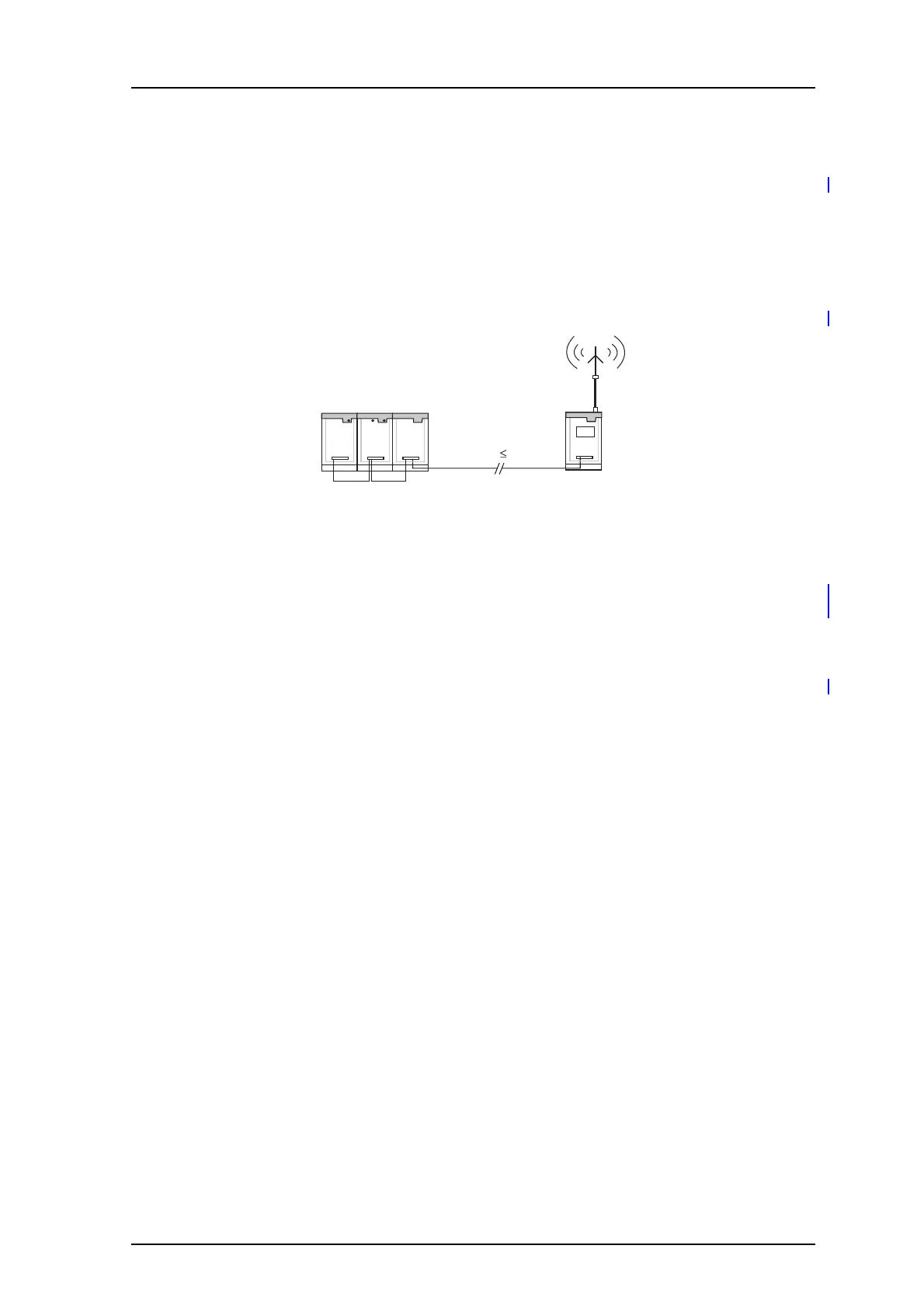
The D-bus is electrically identical with the A-b
us, i.e. maximum 32 units connected with
twisted-pair wiring with a maximum total length of 3 kilometers.
Figure 1. Max D-bus length in UHF- or HF installations.
D-bus 3 km
Terminal
Transmitter
Central
Units
2.1 Frequency Locked Transmitters
The Reference Module, that contains a highly stable reference tone generator, is placed
near the Central Unit. Each transmitter is fitted with the Frequency Lock T952 SM/FL
module. The SM/FL module uses the reference tone to correct carrier frequency.
Equipment for frequency locking
• The Frequency Lock Module T952SM/FL is to be plugged onto the Terminal
T
ransmitter’s circuit board.
• Reference Module T938RM with drive circuits for FL-bus, controlled by the Central
Unit.
Systems with frequency locked transmitters fall into two basic categories: those without
mo
dems to the transmitters, and those that have at least one modem-pair. Three twisted-
pairs carry all communication between the central and terminal transmitter site.
2.2 Without Modem to Transmitters
The transmitters are connected to the D-bus and FL-bus. Several transmitters may be
connected to the D-bus provided if the 3 km max total length is not exceeded. Each
Reference Module has two FL-bus outputs. The D- and FL-buses must be correctly
polarized