TD 90227GB
10 October 2013 / Ver. D
System Installation
Ascom Paging System
13
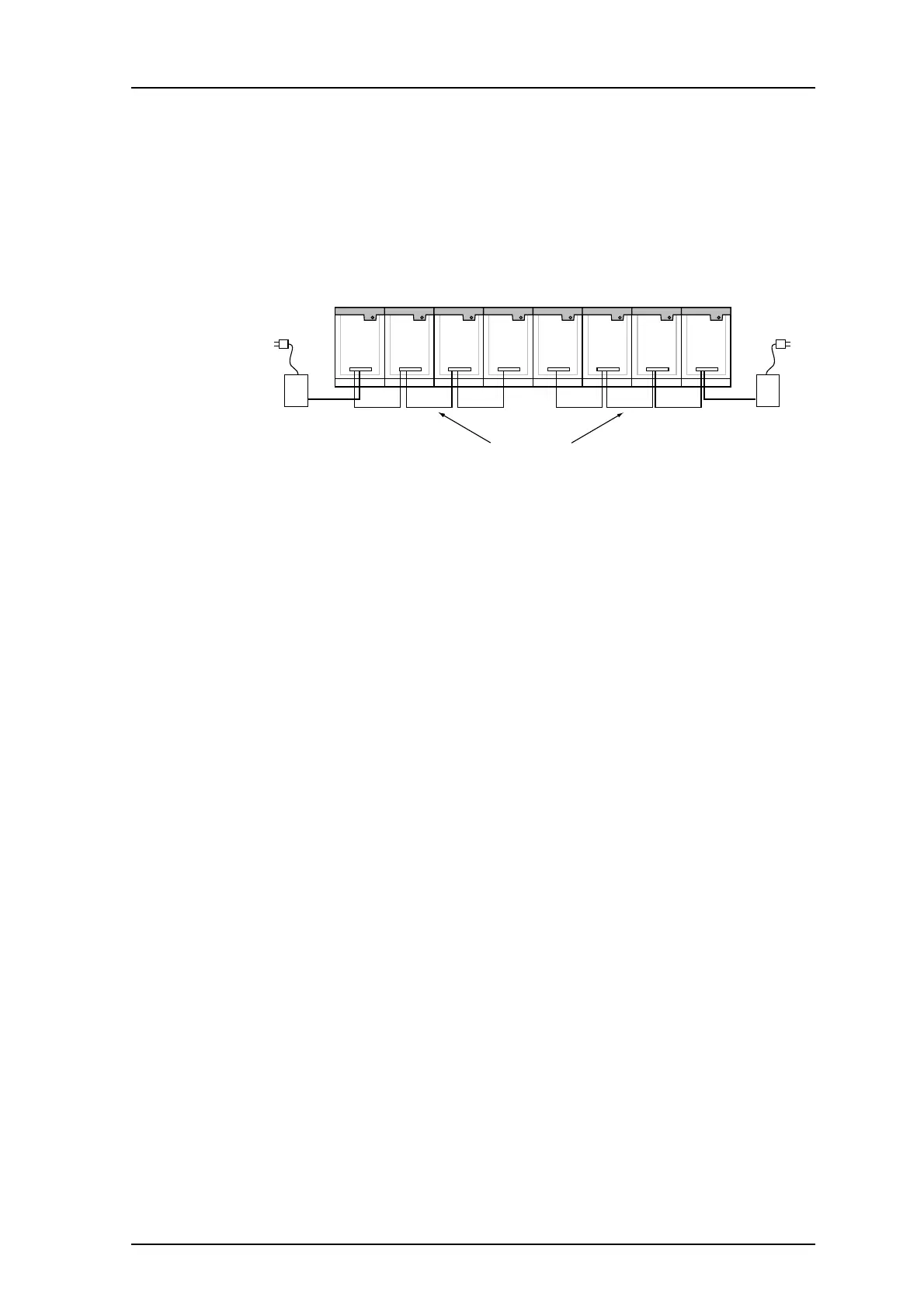
7 Power Supply
All units use 12.5 V DC and can be powered separately, but normally a common power
supply feeds all the units that are placed together in one location. The power supply is
connected to screw terminals on one of the units and then connected in series to the
other units. The wiring from the power supply must be dimensioned so that the voltage
drop to the modules does not exceed 0.5 V at max load. If the total loading exceed the
capacity of the connected power supply, an additional power supply should be used, see
below.
Figure 7. Units powered by two power supplies.