19
4 - Operation
It is possible to configure up to 4 alarms:
AL1, AL2, AL3, AL4 (see pag. 17), select-
ing, for each of them:
A the type and the operating condition of
the alarm
(table 9 page 18)
B the functionality of the alarm acknowl-
edgement (latching)
àltch
C the start-up disabling (blocking) àbloc
D the physical output of the alarm
àOpI àOp2 àOp3
The outputs can be used for alarms if
they are not used as control outputs
(see par. 3.3.5 page12)
It is possible to route up to 4 alarm to a sin-
gle output (OR of the alarms).
Alarm occurrence display
This function can be enabled by the
configuration software.
(please read the user instruction on
the "M5 LINE MODBUS /JBUS PRO-
TOCOL", supplied separately)
The range of the alarm threshold corre-
spond to the whole span and it is not lim-
ited by the SP Setpoint span.
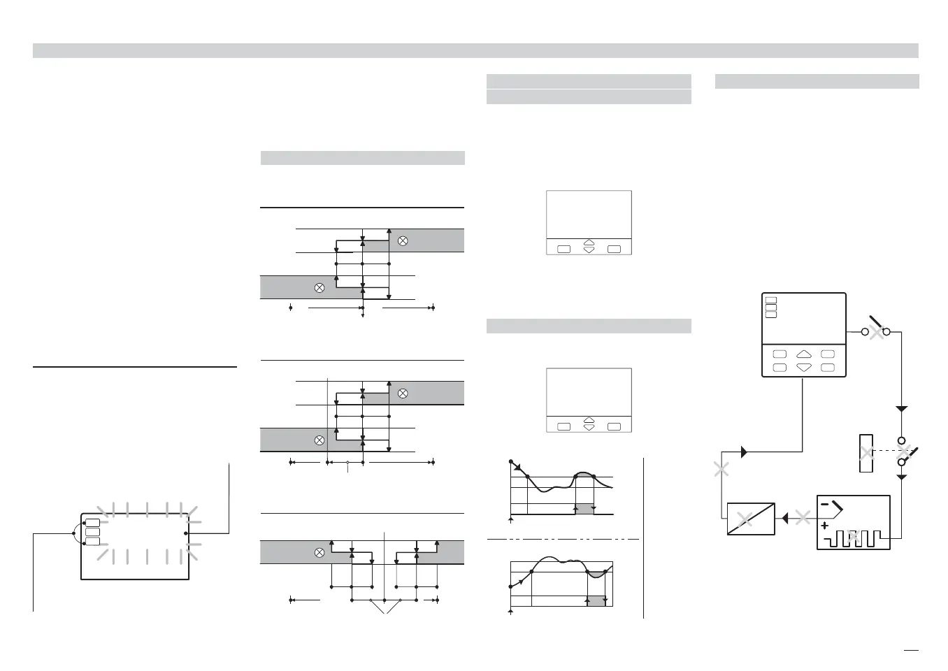
[A] OPERATING CONDITIONS
4.2.1 AL1, AL2, AL3, AL4 ALARMS CONFIGURATION
[B] ALARM ACKNOWLEDGE
FUNCTION
The alarm, once occurred, is presented on
the display until to the time of acknowl-
edge. The acknowledge operation consists
in pressing any key.
After this operation, the alarm leaves the
alarm state only when the alarm condition
is no longer present.
[C] START-UP DISABLING
[D] LOOP BREAK ALARM LBA
When the controller connection to the sen-
sor is discontinued or other faults are
detected in the control loop, the AL1 alarm
becomes active, after a predefined time of
1 to 9999 s, from the detection of the fail-
ure.
The alarm state ceases when the fault con-
dition is no longer present.
275.0
1
2
3
2f.5.H
The red led of the activated alarm output
is on.
The type of alarm is presented
flashing, on the front panel in
alternation with the PV value.
eIn case of ON-OFF control, the LBA
alarm is not active.
∆SP
Disable
SP
On
Off
Start-up
ramp
down
ramp
up
∆SP
Threshold
=
SP ± range
SP
∆SP
On
Off
Disable
Start-up
Absolute alarm
active high
é-fsH
active low
é-fsl
hyd hyu
On
Off
On
Off
Alarm threshold
high rangelow range
Deviation alarm
active high
active low
é-del
hyd hyu
On
Off
On
Off
SP
Alarm threshold
+ range- range
é-deH
Band alarm
active out
é-bnd
hyd hyu
On
Off
SP
Alarm threshold
full scale
full scale
hyd hyu
∆SP
∆SP ∆SP
M5 UK•ed4 10-12-2004 16:20 Pagina 19
 Loading...


