6
2 - Installation
2 INSTALLATION
Installation must only be carried
out by qualified personnel.
Before proceeding with the installation
of this controller, follow the instructions
illustrated in this manual and, partic-
ularly the installation precautions
marked with the B symbol, relat-
ed to the European Community direc-
tive on electrical protection and elec-
tromagnetic compatibility.
B
To prevent hands or metal touching
parts that may be electrically live, the
controllers must be installed in an
enclosure and/or in a cubicle.
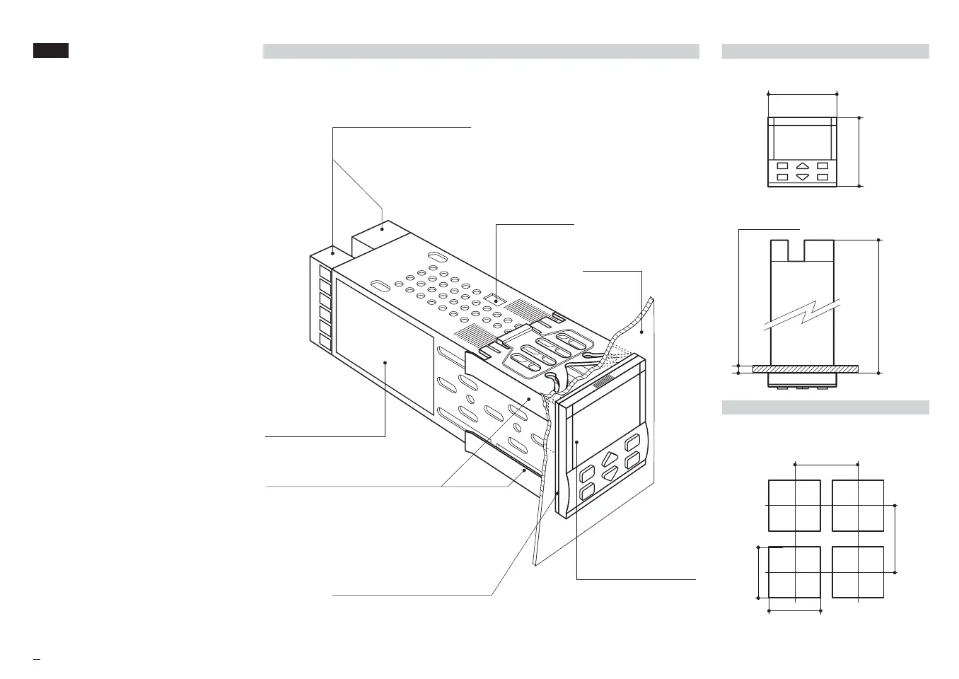
2.1 INSTALLATION DESCRIPTION
Product code label
Sealing front panel gasket
Mounting Clamps
Front Panel
IP65 protection
EN 60529 (IEC 529)
Panel surface
Memory Chip
connector
IP 20 Termination Unit
EN61010 - 1 (IEC1010 - 1)
2.1.1 DIMENSIONAL DETAILS
48 mm
1.89 in
150 mm
5.9 in
20 mm max
0.79 in max
48 mm
1.89 in
2.1.2 PANEL CUT-OUT
65 mm min
2.56 in min
45
+0.6
mm
1.78
+0.023
in
45
+0.6
mm
1.78
+0.023
in
65 mm min
2.56 in min
M5 UK•ed4 10-12-2004 16:20 Pagina 6
 Loading...


