8
3 - Electrical Connections
3 ELECTRICAL
CONNECTIONS
PRECAUTIONS
B
Despite the fact that the instrument
has been designed to work in an
harsh and noisy environmental (level
IV of the industrial standard IEC 801-
4), it is strongly recommended to fol-
low the following suggestions.
A
All the wiring must comply with the
local regulations.
The supply wiring should be routed
away from the power cables.
Avoid to use electromagnetic con-
tactors, power relays and high power
motors nearby.
Avoid power units nearby, especially
if controlled in phase angle
Keep the low level sensor input wires
away from the power lines and the
output cables.
If this is not achievable, use shielded
cables on the sensor input, with the
shield connected to earth.
UL note
[1] Use 60/70 °C copper (Cu) conduc-
tor only.
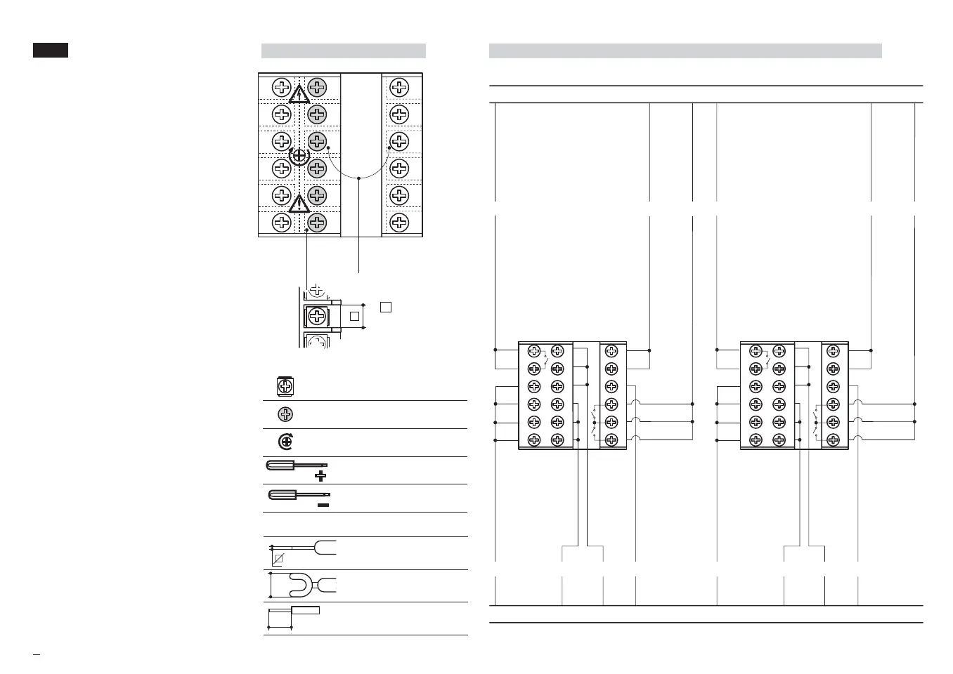
3.1 TERMINATION UNIT [1]
B
3.2 RECOMMENDED ROUTING OF WIRES
B
0,5
Nm
6
5
4
3
2
1
12
11
10
9
8
7
18
17
16
15
14
13
Rear
terminal
covers
Wire size
1 mm
2
(18 AWG
Solid/Stranded)
5.7 mm
0.22 in
6
5
4
3
2
1
12
11
10
9
8
7
18
17
16
15
14
13
6
5
4
3
2
1
12
11
10
9
8
7
18
17
16
15
14
13
Conduit for supply and output cables
Conduit for low level sensor cables
A
L
N
BB
CDE
A
L
N
BB
CDE
A = Supply
B = Relay/Triac Output
C = Analog Inputs
D = Serial
Communication
E = Auxiliary
Inputs/Outputs
F = Digital Inputs
FF
18 screw terminals
Option terminals
Holding screw 0.5 Nm
Positive screw
driver PH1
Negative screw
driver 0,8 x 4 mm
Terminals
Pin connector q 1.4 mm
0.055 in max
Fork-shape AMP 165004
Ø 5.5 mm - 0.21 in
Stripped wire
L 5.5 mm - 0.21 in
M5 UK•ed4 10-12-2004 16:20 Pagina 8