9
3 - Electrical Connections
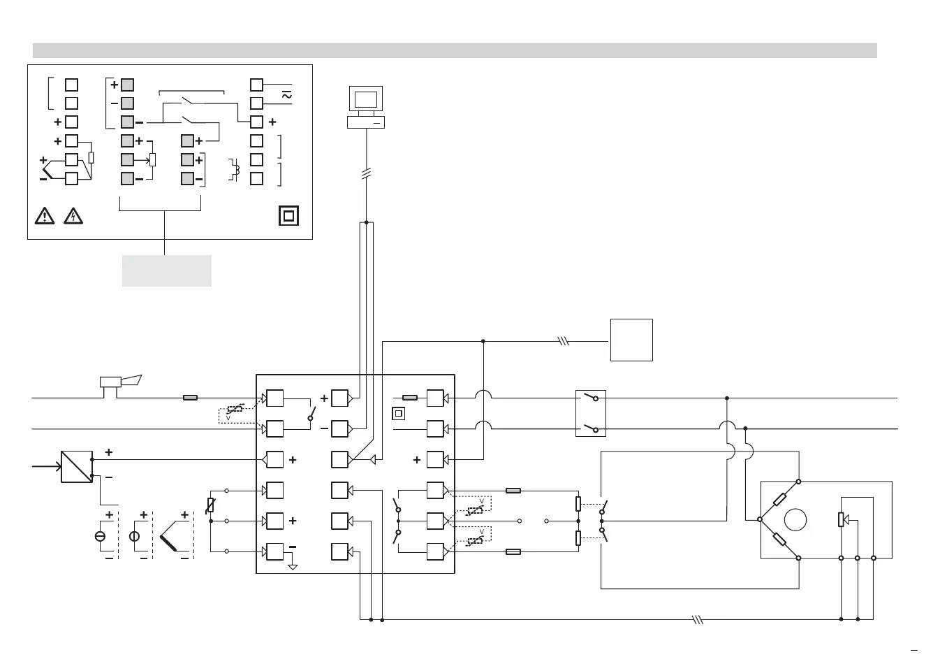
3.3 TYPICAL INSTRUMENT WIRING (valve control)
B
Supervisory
RS485
6
OP1
V
~
18V–
5
4
3
2
1
12
11
10
9
8
7
18
17
16
15
14
13
PTC
OP2
OP3
Supply V
~
L
N
L
N
PV
mA
mV-V Tc
Pt100
A
B
B
2 wires
transmitter
C
Alarm
V
~
Fuse
2A ~T
[6]
V~
Fuse
Fuse
[6]
[6]
Digital
Input
PLC
Commands
Power switch
M
Positioner module
Buffer
relays
Raise
Lower
6
5
4
12
11
10
9
18
17
16
15
14
13
C
RS485
DIGITAL INPUT
mA
V
18 V—
OUT
OP3
OP4
(REM)
N
L
NO
C
TC
CT
OP2
NO
C
NO
[5]
[5]
71
82
3
12
11
10
RTD
POT
100%
0%
OP1
1
2
A
b
B
Option terminals
Notes:
1] Make sure that the power supply volt-
age is the same indicated on the
instrument.
2] Switch on the power supply only after
that all the electrical connections have
been completed.
3] In accordance with the safety regu-
lations, the power supply switch shall
bring the identification of the relevant
instrument. The power supply switch
shall be easily accessible from the
operator.
4] The instrument is PTC protected. In
case of failure it is suggested to return
the instrument to the manufacturer for
repair.
5] To protect the instrument internal cir-
cuits use:
- 2 A
~ T fuses for Relay outputs
- 1 A~ T fuses for Triac outputs
6] Relay contacts are already protected
with varistors.
Only in case of 24 V ~ inductive
loads, use model A51-065-30D7
varistors (on request)
M5 UK•ed4 10-12-2004 16:20 Pagina 9
 Loading...


