10
3 - Electrical Connections
3.3.1 POWER SUPPLY
B
Switching power supply with multiple
isolation and internal fuse
• Standard version:
nominal voltage:
100 - 240V
~ (-15% + 10%)
Frequency 50/60Hz
• Low Voltage version:
Nominal voltage:
24V~ (-25% + 12%)
Frequency 50/60Hz
or 24V– (-15% + 25%)
• Power consumption 3Wmax
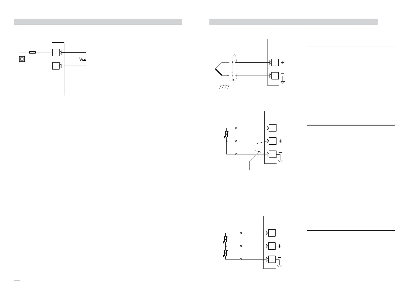
3.3.2 PV CONTROL INPUT
B
A For J L T K S R thermocouple type
• Use always compensation cable of
the correct type for the thermo-
couple used
• Use always compensation cable of
the correct type for the thermo-
couple used
• The shield, if present, must be con-
nected to a proper earth.
B For PT100 resistance
thermometer
• If a 3 wire system is used, use
always cables of the same diame-
ter (1mm
2
min).
Maximum resistance/line 20 Ω
• If a 2 wire system is used, use
always cables of the same diame-
ter (1.5mm
2
min).
A When the distance between the
controller and the sensor is 15
meters, using a cable of 1.5mm
2
diameter, produces an error in the
measure of 1°C .
B1 For ∆T (2x Pt100)
• Use wires of the same length.
Maximum resistance/line 20 Ω
.
R1 + R2 must be <320Ω
6
5
4
A
b
B
When using a 2 wire
system, put a jumper
between terminals 5 and 6
M5 UK•ed4 10-12-2004 16:20 Pagina 10
 Loading...


