- ON : means that the controller uses the control functions.
- STAND-BY : means that the controller does not use any control
function and the display is turned off except for the led Stand-by.
If there is no power, and then power returns, the system always
sets itself in the condition it was in before the black-out.
The ON/Stand-by function can be selected using the key U if the
parameter "t.UF" = 4.
Pressing the key U for at least 1 sec., it is possible to switch the
instrument from the ON status to Stand-by status and vice versa.
4.2 - MEASURING AND DISPLAY
Via the parameter “i.SE” it is possible to select the type of probes
that one wishes to use and which can be: thermistores PTC
KTY81-121 (Pt) or NTC 103AT-2 (nt).
Via the parameter “i.uP”, it is possible to select the temperature
unit of measurement the desired measurement resolution (C0=°C /
1° ; C1=°C / 0.1° ; F0= °F / 1°; F1= °F / 0.1°).
The instrument allows the measuring to be calibrated, that can be
used for re-calibrating the instrument according to application
needs, through the parameters “i.C1”.
Using the parameter “i.Ft”, it is possible to set the time constant
for the software filter for measuring the input values to be able to
reduce the sensitivity to measurement disturbances (increasing the
time).
The normal visualisation on the display is the measured
temperature but it is possible to visualise the highest and lowest
peak measurement values; by quickly pressing and releasing key
U.
The display will alternately show:
“Lt” and the lowest peak temperature
“Ht” and the highest peak temperature
“Pr1” and the instant measured temperature
When the instrument is switched off, such values are always re-set.
However, it is also possible to reset these values if the instrument
is switched on by using the DOWN key hold for 3 sec. during peak
visualization.
The display will show “---” and peaks memory will be reset.
The exit of this visualisation mode occurs automatically 15 seconds
after the last pressing on the key U.
Please remember that visualisation of the probe can be changed
by the defrosting display lock function, by using the parameter
“d.dL” (see defrost function).
4.3 - TEMPERATURE CONTROL
The regulation of the instrument is ON/OFF and acts on the output
depending on the measuring of probe, of the Set Point “SP”, the
intervention differential “r.d” and the function mode “r.HC” .
Depending on the function mode programmed on the parameter
“r.HC” the differential is automatically considered by the regulator
with positive values for a Refrigeration control (“r.HC”=C) or with
negative values for a heating control (“r.HC”=H).
SP
off
ON
r.HC=H
time
r.d
SP
Temp.
r.d
time
r .HC=C
ON ONON ON ON
offoff off
Temp.
Out Out
In the event of probe error, it is possible to set the instrument so
that that the output continues to work in cycles according to the
times programmed in the parameter “r.t1” (activation time) and
“r.t2” (deactivation time).
If an error occurs on the probe the instrument activates the output
for the time “r.t1”, then deactivates it for the time “r.t2” and so on
whilst the error remains.
Programming “r.t1” = oF the output in probe error condition will
remain switched off.
Programming instead “r.t1” to any value and “r.t2” = oF the output
in probe error condition will remain switched on.
Remember that the temperature regulation function can be
conditioned by the “Compressor Protections”, “Delay at power on”
and “Desfrost” functions.
4.4 - COMPRESSOR PROTECTION FUNCTION AND DELAY AT
POWER-ON
The function “Compressor Protection” aims to avoid close start ups
of the compressor controlled by the instrument in cooling
applications.
This function foresees 3 time controls on the switching on of the
output associated with the temperature regulation request.
The protection consists of preventing the output being switched on
during the times set in the parameters “P.P1”, “P.P2” and “P.P3”
and therefore that any activation occurs only after all the times has
finished.
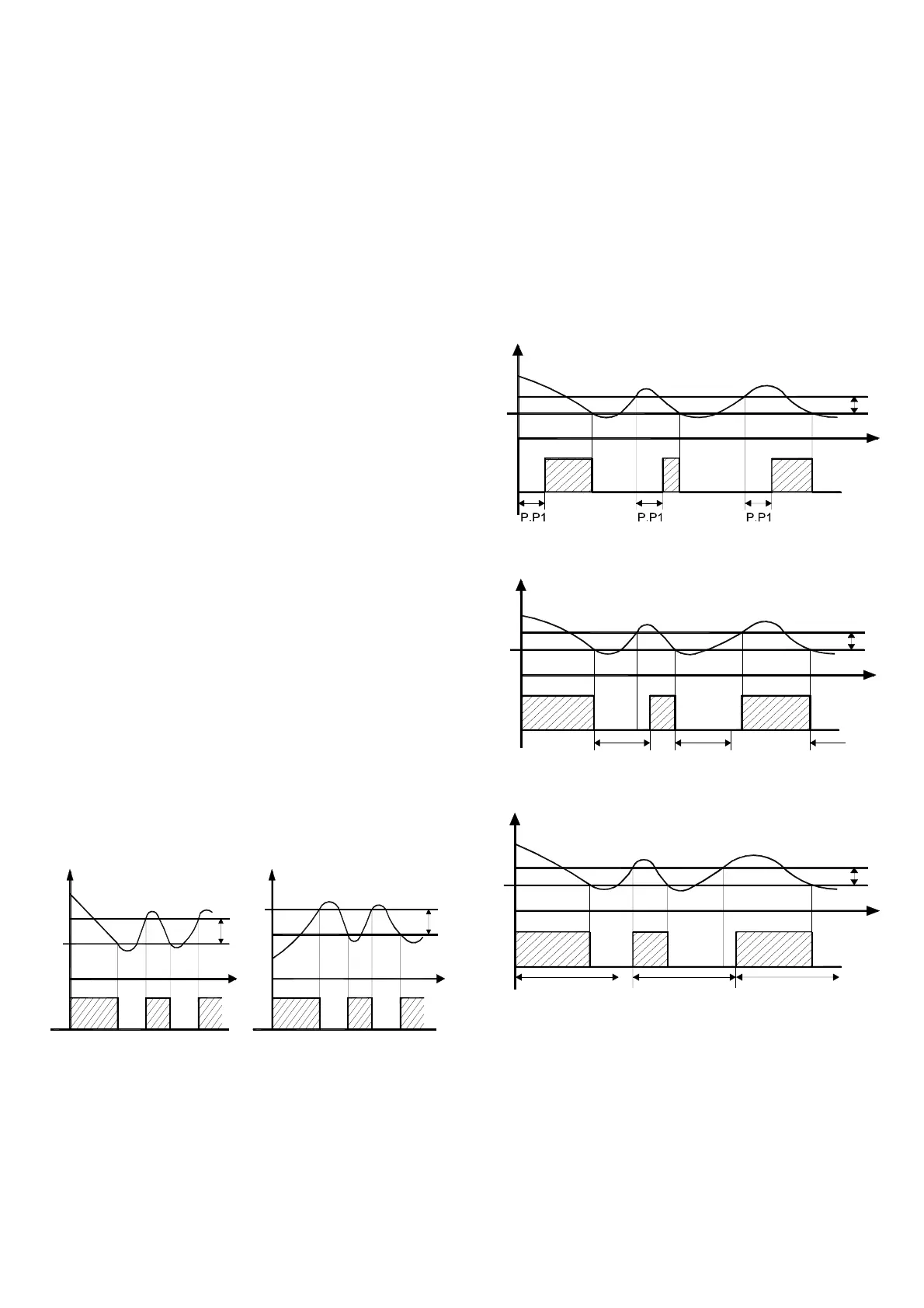
First control (par. “P.P1” ) foresees a delay to the output activation
(switching-on delay).
Temp.
Out
off
ON
SP
time
r.d
off off off
ON ON
Second control (par. “P.P2” ) foresees an inhibition to the
activation of the output by a time delay that starts when the output
is turning off (delay after switching-off).
ON
Out
off
P.P2
P.P2 P.P2
SP
Temp.
time
r.d
ON ON
off off
Third control (par. “P.P3” ) foresees an inhibition to the activation
of the output "Out" by a time delay that starts when the output was
turning on last time (delay between switching-on).
P.P3
Out
off
SP
ON
Temp.
P.P3 P.P3
time
r.d
off off
ON ON
During the output inhibition the led OUT (Cool o Heat) blinking.
It is also possible to prevent activation of the output after the
instrument is turned on, for the time set in the parameter “P.od”.
During the power on delay phase, the display shows the indication
od, alternating with the normal visualisation.
All the functions are disabled by relative parameters = oF.
4.5 - DEFROST CONTROL
The automatic control of defrost, that is by stopping compressor,
occours by interval times
The automatic defrost function is activate when at the parameter
“d.di” is set the defrost interval time.
The first defrost after swiching on can be set by par. “d.Sd”
ASCON TECNOLOGIC - Z31- -OPERATING INSTRUCTIONS- Vr. 02 - 03/12 - ISTR-M
Z31-ENG02 - PAG. 4
Advanced Thermoelectric toll-free 1-866-665-5434 (603) 888-2467 sales@electracool.com

 Loading...