This allows to perform the first defrost to a different interval from
"d.di." time.
If it is desired that to every instrument power on a defrost cycle is
realized program the par. "d.Sd" = oF.
Instead if is desired all defrost to the same interval program "d.Sd"
= "d.di."
Automatic defrost function is disable when “d.di” = oF.
The instrument provides to switch off the output for the time
“d.dE” each “d.di” time (of “d.Sd” in case of first defrost after
power on)
4.5.1 - MANUAL DEFROST
To start up a manual defrosting cycle, press the key UP/DEFROST
when it is not in programming mode and keep it pressed for about
5 seconds after which, if the conditions are correct, the led Defrost
will light up and the instrument will carry out a defrosting cycle.
To stop a defrosting cycle, press the key UP/DEFROST during the
defrost and keep it pressed for about 5 seconds.
4.5.2 - DEFROST DISPLAY LOCK
Through par. “d.dL” and “A.dA” it’s possible to define the display
behaviour during defrost.
The “d.dL” parameter pemits the display visualization lock on the
last temperature reading (“d.dL” = on) during all the defrost cycle
until, at the end of defrost, the temperature has not reached the
lock value or the value [”SP” + “r.d”] or is elapsed the time setted
on par. "A.dA".
Or it permits only the visualization of label “dEF” (“d.dL” = Lb)
during the defrost cycle and, after the defrost, of label “PdF” until,
at the end of defrost, the temperature has not reached the lock
value or the value [”SP” + “r.d”] or is elapsed the time setted on
par. "A.dA".
The display will otherwise (“d.dL”= oF) continue to visualize the
temperature measured by the probe during the defrost cycle.
4.6 - ALARM FUNCTIONS
The alarm conditions of the instrument are:
- Probe errors “E1” , “-E1”
- temperature alarms “Hi” and “Lo”
The alarm functions of the instrument work on the led ALARM and
on the internal buzzer, if present and configured via the parameter
“o.bu”,
The possible selections of the parameter “o.bu” are:
= oF - Buzzer always disable
= 1 - Buzzer signal active alarms only
= 2 - Buzzer signal key pressed only (no alarm)
= 3 - Buzzer signal active alarms and key pressed
Any active alarm is shown on the instrument display with the
lighting up of the ALARM led, the silenced alarm status is shown by
the ALARM led flashing .
The buzzer (if “o.bu” = 1 or 3) is activated in alarm and can be
disabled (alarm silencing) manually by pressing any key of the
instrument .
4.6.1 - TEMPERATURE ALARMS
The temperature alarms work according to the probe
measurement, the type of alarm set in the parameter “A.Ay” the
alarm thresholds set in parameters “A.HA” (maximum alarm) and
“A.LA” (minimum alarm) and the relative differential “A.Ad”.
Through the parameter “A.Ay” it is possible to set the alarm
thresholds “A.HA” and “A.LA” which must be considered as
absolute (“A.Ay”=1) or relative to the Set Point (“A.Ay”=2).
Using some parameters it is also possible to delay the
enablement and the intervention of these alarms.
These parameters are:
“A.PA” - is the temperature alarm exclusion time on switching on
the instrument if the instrument is in alarm status when it is
switched on.
If the instrument is not in alarm status when it is switched on the
time "A.PA" it is not considered.
“A.dA” - is the temperature alarm exclusion time at the end of
defrosting
“A.At” - is the temperature alarm delay activation time
The temperature alarm is enabled at the end of exclusion time and
is enabled after the “A.At” time when the temperature measured by
the probe exceeds or goes below the respective maximum and
minimum alarm thresholds.
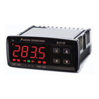
The alarm thresholds will be the same as those set on the
parameters “A.HA” and A.LA” if the alarms are absolute (“A.Ay”=1)
A.Ad
A.Ad
time
AL
off
ON
A.LA
Hi
A.HA
Temp.
Lo
off off
ON
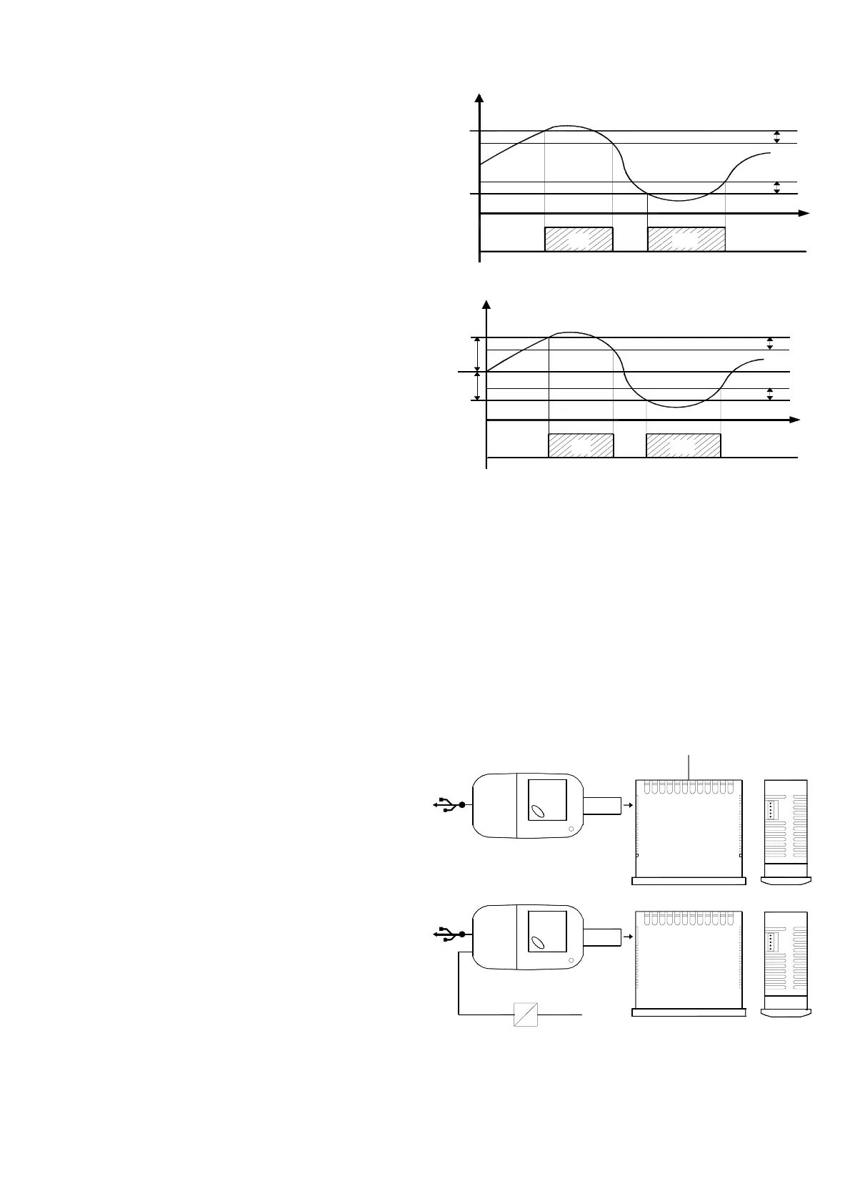
Or values will be [”SP”+”A.HA”] and [”SP”+”A.LA”] if alarms are
relative (“A.Ay”=2).
time
A.Ad
A.Ad
AL
off
ON
Hi
A.LA
SP
A.HA
Temp.
Lo
off off
ON
Temperature alarms of maximum and minimum can be disabled by
setting the parameters "A.HA" and "A.LA" = oF.
4.7 - ACCESSORIES
The instrument is equipped with a connector that allows the
connection of some accessories described as follow.
4.7.1 - PARAMETERS CONFIGURATION BY “A01”
It's possible to upload the complete set of programmed
functional parameters from an instrument to the A01 device via
the 5 pole connector on the instrument. These parameters
may then be downloaded to an unlimited number of
instruments from the A01. The A01 device is mainly used for
the serial programming of instruments that need to have the
same parameter configuration or to keep a copy of the
programming of an instrument and allow its rapid retransmission.
The same device can connect the instrument via USB to a PC and
through the proper configuration software tools "TECNOLOGIC
UniversalConf”, it’s possible to configure the operating parameters.
USB
SUPPLY
AC SUPPLY
SUPPLY ADAPTER
12 VDC
SB
For additional info, please have a look at the A01 instruction
manual.
4.7.2 - “TVRY” REMOTE DISPLAY
To the instrument it is possible to connect the remote display TVR
Y through the special cable that can have a maximum length of 10
ASCON TECNOLOGIC - Z31- -OPERATING INSTRUCTIONS- Vr. 02 - 03/12 - ISTR-MZ31-ENG02 - PAG. 5
Advanced Thermoelectric toll-free 1-866-665-5434 (603) 888-2467 sales@electracool.com
 Loading...