40 m-radialdiaphragmvalve-en-02
13.2 Positioning of the tank valve
The tank valve should be oriented on the vessel head to ensure that it can be fully full
drained. In general, this is on centre of the tank, installed so that the ferrule face of the
valve is horizontal and parallel to the floor.
Ensure that the tank valve actuator can be mounted and dismounted
without any obstructions.
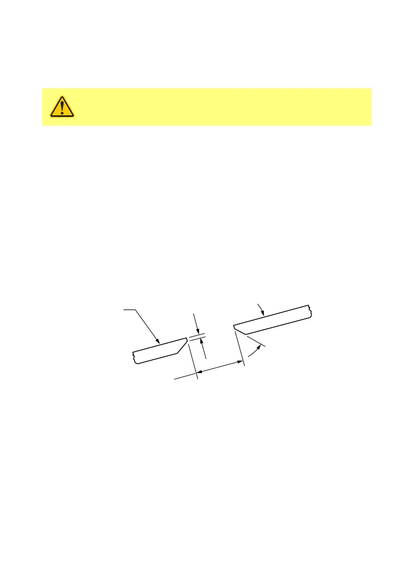
Free distance between welds
The minimum free distance between two welds is specific for each pressure vessel code.
Check the relevant pressure vessel code for the smallest permissible distance (W) between
the weld seam of the tank valve and any other weld.
13.3 Location of tank valve
The location of the tank valve in the dished head should be located so that the
requirements for the actual pressure vessel code are fulfilled.
13.4 Making the hole for the tank valve
After consideration of the previous instructions, the hole for the tank valve should be made
with the same diameter as the tank valve (no more than 1mm (0.040”) larger).
Minimise the air gap between the tank valve and the edge of the hole. The edge of the hole
on the exterior of the head must be ground at a 45 degree angle sloping outwards to
create a weld groove. A straight edge no more than 1.5mm (0.060”) should be left on the
inner edge.
Ø +.040/-.000
Vessel
Head
Max. .060”
Straight
45 ˚Chfr.
Match Valve
13.5 Insertion depth of tank valve
The tank valve must be welded flush to the inner-dished head’s ID surface.
13.6 Welding instructions
Before welding:
• Ensure the heat number on the tank valve matches tank valve material certificate.
• Set up for the TIG welding method unless this conflicts the local pressure vessel
code.
• Prepare to use the proper filler material