Do you have a question about the Ashly FET-200 and is the answer not in the manual?
The Ashly MOS-FET Power Amplifiers, including models FET-200 and FET-500, are designed to replace conventional amplifiers in professional audio applications. These amplifiers leverage MOS-FET (metal-oxide-semiconductor, field-effect-transistor) technology, which combines the desirable operating characteristics of vacuum tubes with the efficiency of transistors, offering superior audio fidelity and enhanced field reliability. The design prioritizes a carefully thought-out, roadworthy, and user-oriented package, aiming for years of maintenance-free service.
A key advantage of MOS-FET technology is its complete immunity to thermal runaway, which is a common failure mechanism in conventional amplifiers. This eliminates the need for elaborate thermal protection circuits and allows for higher quiescent current in the amplifier's output stage, ensuring the output devices operate in their most linear region and resulting in consistently lower distortion. The simpler input drive requirements of MOS-FET devices also contribute to a clean, concise amplifier design, reducing component count and internal wiring, which enhances reliability and compactness.
The Ashly amplifiers are fully complementary, push-pull type with totally discreet, high voltage, and wide bandwidth electronics. This design inherently ensures low noise, low distortion, and excellent transient response. The inputs are bridging, active balanced (transformerless), and equipped with both 1/4" jacks and XLR-type connectors of both sexes, facilitating the linking of multiple amplifiers. All input connections can operate as balanced or unbalanced, determined by the connector used. Stereo, mono, and bridging modes are user-selectable via rear panel switches, eliminating the need for internal modifications or additional components.
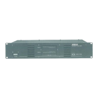
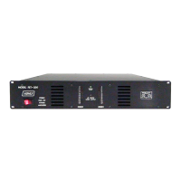
All electronic components are conservatively rated and mounted on a rugged glass-epoxy circuit board. An efficient U-I laminated power transformer saves space and minimizes magnetic flux leakage, allowing other low-level equipment to be mounted nearby without hum interference. Large value, computer-grade electrolytic capacitors are used for long service life. Two 10-segment, 27 dB range LED meter displays provide an easily viewed indication of power levels, and a separate LED indicates thermal overload.
The amplifiers are housed in a rugged, one-piece welded 16-gauge steel chassis with an anodized aluminum front panel and an easily removed steel top cover. The chassis and all internal components are integrated into a single, rigid unit. The FET-500 requires 5 1/4" of rack space, while the FET-200 requires 3 1/2". The power transformer is located near the front of each amplifier, reducing mechanical stress on the chassis. Each channel's electronics and heat sink are combined into a compact, plug-in module that can be removed in seconds, minimizing hard wiring.
Large heat sinks and an aerodynamic internal design allow for an ultra-quiet, slow-speed fan to pull air through the front panel, directly across the heat sinks and power transformer, and out through the rear. This design eliminates the need for ventilation space above or below the amplifier, allowing for economical use of rack space.
The amplifier's output connectors are standard 3/4" spaced combination banana jacks/binding posts, allowing for quick interconnect via banana plugs or bare stranded wire. Bridging output is selected by moving the banana plug to the two center (RED) connectors. Both the AC line and speaker terminals are fuse-protected, and fuses can be replaced instantly without tools. There are no internal fuses.
These amplifiers are designed to be robust and tolerant of various operating conditions. They can handle low impedance, highly reactive loads, and crowded racks. They are highly immune to RF interference and will not be damaged by intermittent short circuits; sustained shorts will simply blow the output fuse. Due to their balanced circuit design, delay circuits and output relays are unnecessary, meaning there is no turn-on thump, and volume controls can remain up when power is applied and removed. Both amplifiers can continue operating through a brown-out, even when line voltages drop as low as 20 volts.
For installation, Ashly MOS-FET amplifiers are designed to mount in a standard 19" equipment rack. Forced-air cooling means no ventilation space is required above or below the amplifier, allowing for efficient rack space use and multiple stacking. The only precaution is to ensure the front panel air inlets and rear panel fan outlet remain unobstructed. The use of four front panel screws is recommended to evenly distribute stress on the panel. While the chassis is strong enough for permanent installations or occasional movement, rear support is suggested for amplifiers frequently in transit. All amplifiers should be connected to a 3-wire grounded outlet supplying 120 Volts 50-60Hz.
In stereo operation, connections are straightforward, with each channel having its own input and output. For mono operation, depressing the MONO switch directs the Channel 1 input to both sides of the amplifier, with volume controlled by the Channel 1 LEVEL control. In bridging mode, both the MONO and BRIDGING switches are depressed. Channel 1 input feeds both sides, but the phase of Channel 2 amplifier is inverted 180 degrees, and the speaker connection is made to the two RED output jacks, with the black output jacks unused.
The front panel meters respond to the peak output voltage at the speaker terminals. A ten-segment, three-color LED display covers a twenty-seven decibel range. If all LEDs on one channel light up and stay on with only a small input signal, it indicates a blown speaker fuse or faulty speaker wiring.
The thermal status indicator, a green LED, turns off if the amplifier overheats, signaling an automatic shutdown. The fan continues to run, and when the heat sink temperature returns to normal, the green THERMAL STATUS LED will illuminate, and the amplifier will turn back on. Overheating is unlikely under normal use, but if it occurs, checking for blocked airflow in front of and behind the amplifier is advised. A generous safety margin exists between the temperature required to activate thermal cutouts and temperatures that could damage components.
The input of Ashly amplifiers is a balanced bridging type with a 10k ohm impedance, providing superior hum and noise rejection while eliminating ground loops. It can also be used in a single-ended, unbalanced mode with unbalanced input connectors. Each channel offers 1/4" jacks or XLR input connectors, all in parallel. Only one connector is used as an input at a time, while others can jumper to other amplifiers. Signal connections for 1/4" stereo phone jacks are: tip for in-phase (+), ring for out-of-phase (-), and sleeve for chassis ground/shield. For XLR connectors: pin 3 for in-phase (+), pin 2 for out-of-phase (-), and pin 1 for chassis ground/shield. When feeding from an unbalanced source, either an XLR connector or a standard stereo 1/4" phone plug can be used, connecting the signal "hot" to XLR pin 3 or the phone plug tip, and signal ground to XLR pins 1 and 2 or the phone plug's ring and sleeve. A standard 1/4" mono phone plug automatically connects ring and sleeve. To avoid ground loops when the amplifier is physically mounted in the same rack as the signal source, an alternate connection system can be used: signal hot to XLR pin 3 or phone plug tip, and signal ground to XLR pin 2 or phone plug ring, leaving XLR pin 1 and the jack sleeve unconnected.
| Power Output | 200W |
|---|---|
| Total Harmonic Distortion | <0.1% |
| Damping Factor | > 200 |
| Input Impedance | 20 kOhms |
| Cooling | Convection |
| Signal to Noise Ratio | > 100 dB |
| Type | Power Amplifier |
| Frequency Response | 20 Hz - 20 kHz |
| Dimensions | 19" x 1.75" x 12" |