VAR8 / Variants - Installation Guide
ENHANCED
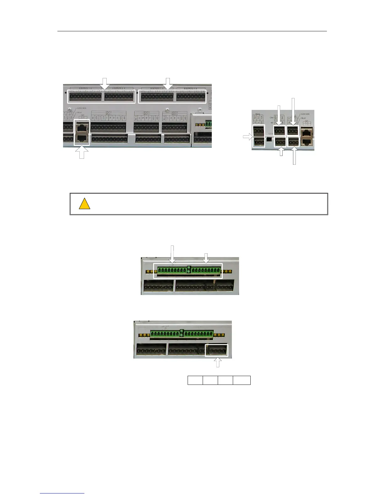
AUDIO A OUTPUTS
(ON EXP8 ONLY)
STANDARD
AUDIO OUTPUTS
ENHANCED
AUDIO B OUTPUTS
(ON EXP8 ONLY)
RS232
RS485
FAULT RELAY
CAN BUS
AUDIO MONITORING
(See pinout in Table 1, page 13.)
4. Connect the rack and field cabling for the network interface (if the ANIC8 Network Interface Card
is used).
Wiring should be according to the diagram shown in Figure 2 on page 7 for EMC
compliance.
!
!
Figure 1 on page 5 shows details of each connector. Section “2 Connections” on page 12
describes the signals.
NETWORK UPSTREAM
NETWORK DOWNSTREAM
5. Connect the dual power supply (as appropriate) to the rear panel connector.
Section “2 Connections” on page 12 describes the signals.
POWER SUPPLY
GND +V GND +V
6. The installation is now complete and ready for system commissioning.
Refer to the Commissioning Guide [Table 2 - 3].
Issue: 01 complete, approved
Page 10 of 22