VAR8 / Variants - Installation Guide
1.2 Recommended Installation Procedure
Please read and observe the “Safety and Precautions” section on page 20 of this
manual.
1. If installing a VAR8 with a Network Interface Card, note that the Network Interface Card is
configured, by default, for network operation using 3 audio network channels. If stand-alone
operation or 1 or 2 channel only network operation is required, set the links on the Router board
as described in Section “1.3 Link Settings for Stand-Alone, 1 or 2 Channel Only Network
Operation” on page 11.
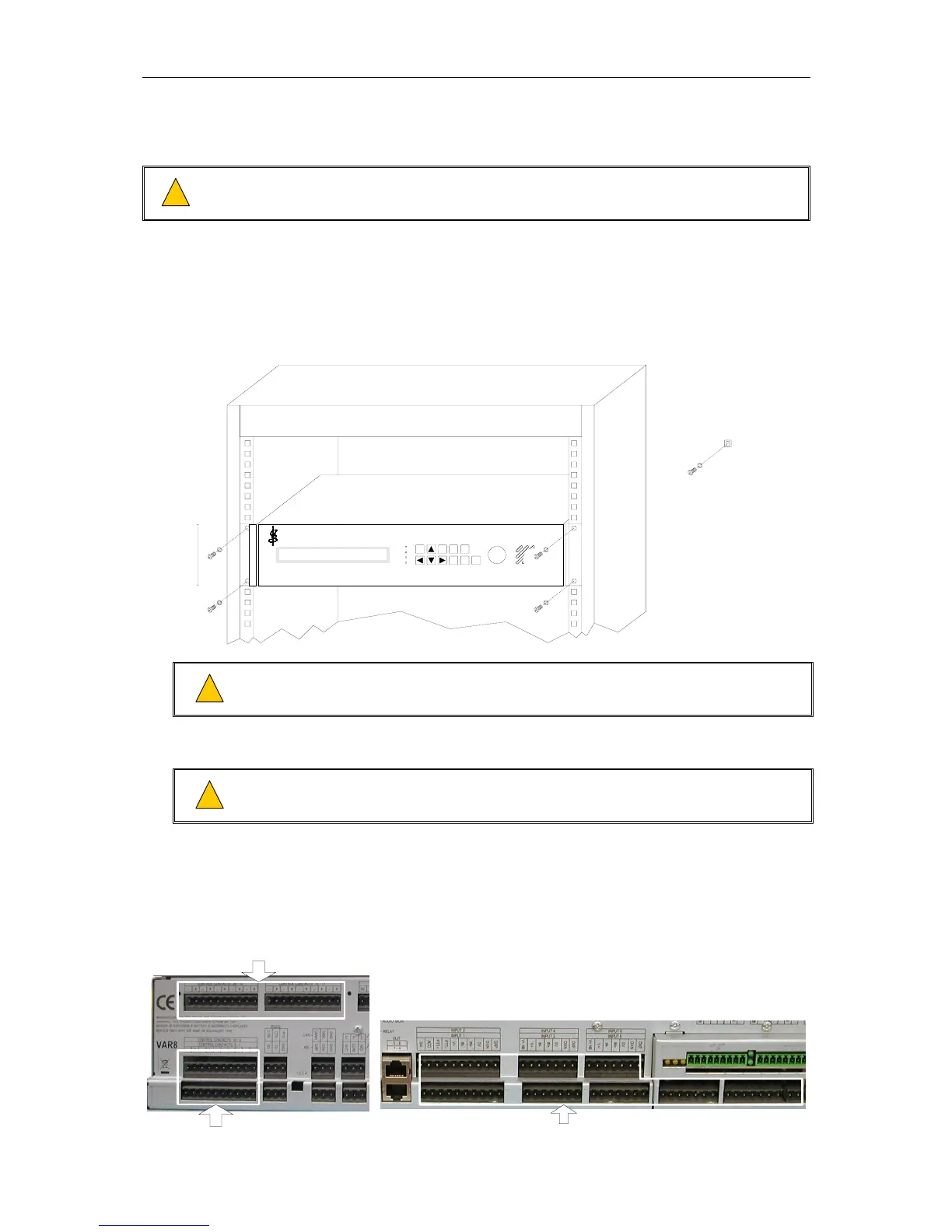
2. Mount the VAR8 into a 19-inch standard equipment rack.
DSP Audio Router
power
processor
comms
fault
SELECT BACK
DEFAULT
LAMP
TEST
FAULT
CLEAR
FAULT
ACCEPT
AUDIO
MON
2U
M6 PAN HEAD POZIDRIV SCREW
M6 PLAIN WASHER
M6 CAGE NUT
Ensure that there is at least 1U of ventilated space between the unit and any source
of heat (e.g. V400 amplifier mainframes).
3. Connect the rack and field cabling for control ports, audio inputs, audio outputs, signal monitoring,
CAN bus, RS232, and RS485, as appropriate.
Wiring to each VAR8 connector should be according to the diagram shown in Figure
3 on page 8 for EMC compliance.
!
!
!
!
!
!
The following drawings indicate the position of the connectors on the rear panel. Note that upper
control port, A/B output, and network interface connectors may not be present, depending on the
VAR8 variant being installed.
Figure 1 on page 5 shows details of each connector. Section “2 Connections” on page 12
describes the signals.
CONTROL PORTS
ADDITIONAL CONTROL PORTS
(ON EXP8 ONLY)
AUDIO INPUTS
Issue: 01 complete, approved
Page 9 of 22