EasyManua.ls Logo

ASP STERRAD 100 - Service Manual

Default Icon
309 pages
Print Icon
To Next Page IconTo Next Page
Loading...
STERRAD
100 Sterilization System
Service Guide
Advanced Sterilization Products
33 Technology
Irvine, California 92618
1-888-STERRAD
TS-02859-0-002 REV D
This guide contains information on servicing the STERRAD
®
100 S Sterilizer. The
STERRAD 100 S Sterilizer is for international use only. No use other than testing related
to the development and submission of information to the FDA is authorized in the
United States.

Table of Contents

Question and Answer IconNeed help?

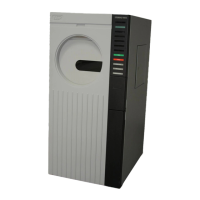
Do you have a question about the ASP STERRAD 100 and is the answer not in the manual?

Summary

Chapter 1. About the Service Guide

Introduction

Provides an overview of the service guide's purpose and content.

Whats New in this Guide?

Highlights changes and new features in the current revision of the guide.

Revision C Information

Details information specific to Revision C updates and corrections.

REV A;B Information

Provides details on changes and information from Rev A/B.

What’s New Table

Summarizes changes across different sections and revisions.

Chapter 2. System Operation

Introduction

Introduces the chapter on system operation and its scope.

Theory of Operation-Overview

Explains the fundamental principles of the STERRAD sterilization process.

Routine Maintenance

Details operator and technician maintenance tasks for the sterilizer.

Alarm Limits By Parameter

Lists alarm limits and their corresponding process equipment specifications.

Software Overview

Describes the role and function of the system software.

Software Safety Considerations

Outlines safety features and shutdown functions built into the software.

User Interface and Operator Controls

Explains the controls and interface panel used by the operator.

STERRAD 100 S Theory of Operation

Details the specific theory of operation for the STERRAD 100 S system.

Chapter 3. System Messages

Introduction

Introduces the chapter on system messages and their interpretation.

Using System Messages

Provides guidance on how to effectively use and troubleshoot system messages.

CASSETTE INSERTED INCORRECTLY

Describes issues related to incorrect cassette insertion and troubleshooting steps.

Door Stuck in Closed Position

Details troubleshooting for a door stuck in the closed position.

Suspected Leak

Identifies conditions indicative of a leak and troubleshooting steps.

RF Amplifier Problems

Addresses issues related to the RF amplifier failing or underperforming.

Leak Identification Tips

Provides methods for identifying the source of leaks within the system.

Chapter 4. Vacuum Subsystem

Introduction

Introduces the vacuum subsystem and its components.

Different Subsystem Configurations

Explains variations in vacuum subsystem configurations across system versions.

Theory of Operation

Details the operational principles of the vacuum subsystem.

Vacuum Pump

Describes the function and operation of the vacuum pump.

Vacuum Subsystem Calibration

Outlines procedures for calibrating the vacuum subsystem.

Adjusting The Vacuum Switch

Provides steps for adjusting the vacuum switch settings.

Removal;Replacement Procedures

Details the steps for removing and replacing vacuum subsystem components.

Attaching the Pump

Guides on attaching the vacuum pump during installation or replacement.

Chapter 5. Injection Subsystem

Introduction

Introduces the injection subsystem and its components.

Theory of Operation-Injection Subsystem

Details the operational principles of the injection subsystem.

Cassettes

Describes the hydrogen peroxide cassettes used in the system.

Injection Subsystem Calibration

Outlines procedures for calibrating the injection subsystem.

Injector Valve Height

Details the procedure for adjusting the injector valve height.

Cassette Optics

Covers the calibration of cassette optics for proper tracking.

Injector Pump Floating Guide Adjustment

Explains how to adjust the injector pump floating guide.

Injection Subsystem Removal;Replacement

Provides steps for removing and replacing injection subsystem components.

Remove the Injector Pump

Details the procedure for removing the injector pump.

Chapter 6. User Interface and Control Subsystems

Introduction

Introduces the user interface and control subsystems.

Theory of Operation

Describes the operational principles of the user interface and control subsystems.

Software Safety Considerations

Outlines safety features and shutdown functions of the system software.

Controller Operation

Explains how the controller subsystem manages machine functions.

User Interface Calibration

Provides procedures for calibrating the user interface components.

Setting the Printer DIP Switches

Guides on configuring the printer's DIP switches.

Setting System Parameters

Covers settings that track system activities and defaults.

Master Reset

Details the procedure for performing a master reset of the system.

Controller Calibration

Outlines procedures for calibrating the controller subsystem.

Chapter 7. Door and Chamber Subsystem

Introduction

Introduces the door and chamber subsystems.

Door and Chamber Theory of Operation

Explains the operational principles of the door and chamber.

Calibration

Covers calibration procedures for the door and chamber subsystems.

Door and Chamber Temperature

Details testing and calibration for door and chamber temperatures.

Door Top, Bottom, And Over Center Sensors

Explains the function and alignment of door sensors.

Door Open Close Speed

Describes procedures for adjusting the door's open and close speed.

Door and Chamber Alignment

Provides steps for aligning the chamber, frame, and door.

Removal;Replacement

Details procedures for removing and replacing door and chamber components.

Remove the Electrode and Spacers

Guides on removing the electrode and its associated spacers.

Chamber Heaters Removal;Replacement

Details the process of removing and replacing chamber heaters.

Remove;Replace the Feedthrough

Guides on removing and replacing the chamber feedthrough.

Remove the Sight Glass

Details the procedure for removing the sight glass.

Chapter 8. Pneumatic Subsystem

Introduction

Introduces the pneumatic subsystem and its components.

Pneumatic Theory of Operation

Explains the principles of operation for the pneumatic subsystem.

Pneumatics Calibration

Outlines calibration procedures for the pneumatic subsystem.

Pneumatics Pressure Switch

Details the function and calibration of the pneumatic pressure switch.

Pneumatics Removal;Replacement Procedures

Provides steps for removing and replacing pneumatic components.

Chapter 9. AC Subsystem

Introduction

Introduces the AC interface and subsystem.

AC Subsystem Theory of Operation

Explains the power delivery principles of the AC subsystem.

AC Calibration

States that AC calibration is not required but verification is needed.

AC Removal;Replacement

Details procedures for removing and replacing AC subsystem components.

Remove the AC Enclosure

Guides on removing the AC enclosure.

Replace the Solid State Relay Board

Details replacing the solid state relay board.

Chapter 10. Radio Frequency (RF) Subsystem

Introduction

Introduces the radio frequency (RF) subsystem.

RF Theory of Operation

Explains the principles of operation for the RF subsystem.

RF Calibration

Notes RF calibration is performed during AutoTest procedures.

RF Removal;Replacement

Outlines procedures for RF subsystem removal and replacement.

Remove the RF Enclosure

Guides on removing the RF enclosure.

Remove the RF Match

Details the procedure for removing the RF match component.

Chapter 11. System Installation

Introduction

Introduces the system installation process.

Pre-Installation

Outlines essential steps to perform before uncrating the system.

Uncrating the System

Provides detailed steps for safely uncrating the sterilization system.

Installing the Seismic Restraints

Details the procedure for installing seismic restraints for safety.

Preparing The System For Use

Covers final steps to prepare the system for operation.

Initialization

Explains the sequence for initializing the system prior to use.

Master Resets

Details various reset procedures for system initialization and troubleshooting.

System Acceptance

Describes the process for certifying system performance post-installation.

Software Installation

Guides on installing the system software, including language settings.

Verify Voltages

Outlines procedures for verifying system voltages after installation.

Chapter 12. Planned Maintenance

Introduction

Introduces the planned maintenance requirements for the sterilizer.

Maintenance Schedule

Provides a schedule for PM1 and PM2 maintenance tasks.

Level 1 Planned Maintenance

Details the procedures for Level 1 planned maintenance tasks.

Seismic Restraint Inspection

Covers inspection of seismic restraints as part of Level 1 maintenance.

Replace Vacuum Pump Oil

Guides on replacing the vacuum pump oil.

Level 2 Planned Maintenance

Details the procedures for Level 2 planned maintenance tasks.

Replace Exhaust Filters

Guides on replacing the exhaust filters or catalytic converter.

Replace Pump Intake Filter

Details replacing the pump intake filter.

Replace the HEPA Filter

Guides on replacing the HEPA filter element.

Door and Chamber Procedures

Covers cleaning and maintenance procedures for the door and chamber.

Chapter 13. Product Certification

Introduction

Introduces the product certification procedures.

Certification Procedures

Lists the sequence of procedures required for system certification.

System Preparation

Details steps for preparing the system before performing certification tests.

Compressor Pressure Switch Test

Verifies the starting and shut-off pressure of the pneumatics compressor.

Power Supplies Test

Tests the performance and voltage output of the system's power supplies.

Analog to Digital Set Point Test

Verifies the accuracy of analog-to-digital conversion for set points.

Baratron Zero Test

Tests the zero calibration of the Baratron capacitance manometer.

Injector Pump Floating Guide Check

Ensures proper cassette tracking and guide alignment.

RF Power Test

Tests the output power of the RF generator.

Leak Back Test

Verifies the system's leak rate to ensure vacuum integrity.

Heater Voltages and Temperatures

Details procedures for testing heater voltages and temperatures.

Appendix A. Technical Data

Overview

Provides a general overview of the technical specifications.

Physical Specifications

Lists the physical dimensions, weight, and chamber specifications.

Environmental Conditions

Details transport, storage, and operation environmental parameters.

Electrical Requirements

Specifies voltage, phase rotation, and connection requirements.

Heater Impedance

Lists the impedance values for various heaters in the system.

Tools and Test Equipment

Lists necessary tools and test equipment for service procedures.

Appendix B. AutoTest

Introduction

Introduces the AutoTest board and its function.

Overview

Provides an overview of the AutoTest's selectable tests and reference information.

User Interface Tests

Details tests for verifying the functionality of the user interface components.

Membrane Switch Test

Tests the functionality of each membrane switch on the control panel.

Lamps Test

Steps through checking the various display panel lights for proper operation.

Sensor Tests

Covers tests for various sensors, including door, cassette, and vacuum switches.

Door Sensor Tests

Details specific tests for the door's top, bottom, and center sensors.

Injection and Pneumatics Tests

Covers tests for the injector pump pawl, motor, and injection process.

Throttle Valve;Heater Menus

Includes tests for throttle valve cycling and heater operation.

Chamber;Door Heaters Test

Tests the operation and voltage of chamber and door heaters.

Analog Test

Verifies analog inputs and readings from various sensors.

Vacuum Subsystem Tests

Covers tests for vacuum pump rotation and RF interaction.

Leak Back Test

Performs a test to verify the system's leak rate.

Cassette Adjustments

Guides on adjusting cassette tracking and fiber optic amplifier calibration.

Printer Test

Tests the functionality and output of the system printer.

STERRAD 100 Schematics

Functional Diagram

Provides a high-level functional block diagram of the system.

Cable interconnect diagram 10-01810-1-100-A Block 1.8

Schematic detailing cable interconnections for Block 1.8 systems.

Cable interconnect diagram 10-03252-0-100-A Block 2.

Schematic detailing cable interconnections for Block 2 systems.

Pneumatic flow schematic 10-00189-1-100 D

Pneumatic system flow schematic diagram.

Control panel PCB 10-00952-100-F Block 1.8

Schematic for the control panel PCB for Block 1.8.

Solid state relay PCB 10-00974-100-E Block 1.8

Schematic for the solid state relay PCB for Block 1.8.

Stepper motor driver PCB 10-01090-100-F

Schematic for the stepper motor driver PCB.

AC distribution elementary diagram 10-02270-0-100-C Block 2

Elementary diagram for AC distribution in Block 2.

ASP STERRAD 100 Specifications

General IconGeneral
BrandASP
ModelSTERRAD 100
CategoryLaboratory Equipment
LanguageEnglish

Related product manuals