EasyManua.ls Logo

Aspen AEU Series - User Manual

Aspen AEU Series
12 pages
Print Icon
To Next Page IconTo Next Page
Loading...
1
`
INSTALLATION GUIDE
AEU & AED Series - Manufactured Housing
Electric Furnace Kit
1. Safety Instruction
!
WARNING
Potential safety hazards are alerted using the following symbols. The symbol is used in conjunction with terms
that indicate the intensity of the hazard.
This symbol indicates a potentially hazardous situation, which if not avoided,
could result in serious injury, property damage, product damage or death.
This symbol indicates a potentially hazardous situation, which if not avoided,
may result in moderate injury or property damage.
CAUTION
!
Only factory authorized kits and acces-
sories should be used when installing or
modifying this unit unless it is so noted in
these instructions. Some localities may require a licensed
installer/service personnel.
CAUTION
!
Certied technicians or those individuals
meeting the requirements specied by
NATE may use this information. Property
and product damage or personal injury hazard may occur
without such background.
!
WARNING
All power sources should be disconnect-
ed prior to servicing. Failure to do so may
cause personal injury or property dam-
age.
!
WARNING
Product designed and manufactured to
permit installation in accordance with lo-
cal and national building codes. It is the
installers responsibility to ensure that product is installed
in strict compliance with national and local codes. Manufac-
turer takes no responsibility for damage (personal, product
or property) caused due to installations violating regula-
tions. In absence of local/state codes, refer to National Elec-
tric Code: NFPA 90A & 90B Uniform Mechanical Code.
!
WARNING
When this unit is installed in an enclosed
area, such as a garage or utility room with
any Carbon Monoxide producing devices
(i.e. automobile, space heater, water heater etc.) ensure that
the enclosed area is properly ventilated.
!
WARNING
The unit is designed for operation with
208/240 V, single phase, 60 Hz power
supply. Aspen will not be responsible for
damages caused due to modication of the unit to operate
with alternative power sources.
!
WARNING
Unit is not approved for outdoor installa-
tions.
!
WARNING
3. Installation Preparation
3A. Clearances
Read all the instructions in this guideline carefully while paying spe-
cial attention to the WARNING and CAUTION alerts. If any of the
instructions are unclear; clarify with certied technicians. Gather all
the tools needed for successful installation of the unit prior to begin-
ning the installation.
This unit is designed for zero clearance installation on three sides
and adequate clearance to provide access for service in the front. A
minimum of 18” (alcove) or 6” (closet) clearance is recommended on
the front end (Fig 3A-1).
For closet installation, the return air opening can be on the front door,
above the furnace casing on a wall, or on the electric door’s louvered
door (If applicable.)
A minimum clearance of six inches is required, on the return side, in
order to allow for proper airow.
Fig 3A-1. Minimum Clearance for Electric Furnace
2. Inspection
ü On receiving the product, visually inspect it for any major shipping
related damages. Shipping damages are the carrier’s responsibility.
Inspect the product labels to verify the model number and options
are in accordance with your order. Manufacturer will not accept dam-
age claims for incorrectly shipped product.
18” for Alcove
6” for Closet
0”
0”
6”
Question and Answer IconNeed help?

Do you have a question about the Aspen AEU Series and is the answer not in the manual?

Summary

Safety Instructions and Warnings

Hazard Symbols and Safety Alerts

Explanation of hazard symbols (WARNING, CAUTION) and associated safety alerts.

Pre-Installation Safety Precautions

Essential safety measures before installation, including power disconnection and ventilation.

Product Inspection and Preparation

Installation Clearance Requirements

Required clearances for closet and alcove installations and front service access.

Closet and Alcove Installation

AEU-000 Configuration

Steps for configuring the AEU-000 model for closet or alcove installation.

Electrical Line Voltage Wiring

Wiring for Single;Three Phase Power

Guidance on wiring units for 208/240 volts, single or three-phase power supply.

Air Volume Adjustment

Setting Air Volume for System Cooling

Procedure for adjusting air volume to match outdoor unit requirements for cooling capacity.

System Charging and Charging Procedures

System Charging Process

Steps for charging the refrigeration system, including evacuation and charge adjustment.

Final System Checkout

Post-Installation System Checks

Final checks including cabinet sealing, condensate leaks, refrigerant inspection, and securing doors.

Wiring Diagram

AEU;AED Models Wiring Diagram

Detailed wiring diagram for AEU/AED models, including component codes and wiring notes.

Overview

This document provides installation and maintenance guidelines for the Aspen AEU & AED Series Manufactured Housing Electric Furnace Kit. It emphasizes safety, proper installation, and regular maintenance to ensure optimal performance and longevity of the unit.

Function Description

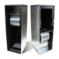
The Aspen AEU & AED Series Electric Furnace Kit is designed for use in manufactured housing to provide heating and, when combined with an outdoor unit, cooling. These units are designed for single or three-phase 208/240 volts, 60 Hz power supply. The electric furnace utilizes a PSC motor for air circulation and can be configured for various airflow orientations (upflow, downflow, top return, front return, top/front return) to suit different installation requirements. The system is designed to integrate with an outdoor condensing unit for cooling, with the electric furnace managing indoor air circulation and electric heat.

The unit's primary function is to heat the indoor air using electric resistance heaters. It also includes a blower to circulate air throughout the duct system. For cooling, the electric furnace works in conjunction with an outdoor condensing unit, with the indoor blower facilitating the circulation of cooled air. The system includes a low voltage transformer to manage control circuits and various safety features to ensure safe operation.

Usage Features

The Aspen electric furnace offers several usage features designed for flexibility and ease of integration into manufactured homes:

  • Zero Clearance Installation: The unit is designed for zero clearance installation on three sides, allowing for flexible placement in closets or alcoves. A minimum of 18 inches (alcove) or 6 inches (closet) clearance is recommended on the front for service access.
  • Configurable Airflow: The unit can be configured for different airflow orientations:
    • AEU-000 (Upflow/Bottom Return): This is the default configuration for upflow operation with return air entering from the bottom.
    • AED-000 (Downflow/Top Return): Configurable for downflow operation with return air from the top.
    • AED-001 (Downflow/Front Return): Configurable for downflow operation with return air from the front.
    • AED-002 (Downflow/Top & Front Return): Configurable for downflow operation with return air from both the top and front.
  • Conversion Kits: The manual details various conversion kits (AEDK-01, AEDK-02, AEDK-03, AEDK-04, AEDK-05, AEDK-06, AEDK-07) that allow installers to reconfigure the unit's airflow and return air options. These kits often involve reorienting components, adding or removing doors (solid or louvered), and adjusting filter placement.
  • Single Stage Cooling with Electric Heat: The electric furnace comes factory-setup for a single-stage cooling system. If accessory electric heaters are preinstalled, the unit will also have a low voltage wire for electric heat control.
  • Time Delay Relay: During cooling mode, a time delay relay inside the electric furnace energizes the indoor blower G wire. After a short delay, the relay contacts close, applying power to the blower motor. Fan delay periods are 7 seconds ON delay and 65 seconds OFF delay. For heating, the blower delays for 5 seconds ON and 60 seconds OFF.
  • Ductwork Integration: The unit is designed to integrate with standard duct systems, with recommendations for non-flammable flexible collars for return and discharge connections to prevent vibration transmission. Duct connectors are used to seal the unit to the floor opening.
  • Electrical Wiring: The unit supports single or three-phase 208/240V, 60 Hz power supply. Wiring should adhere to National Electric Code and local codes, accommodating both copper and aluminum wiring. The low voltage transformer can be adjusted for 208V or 240V input to ensure correct secondary output voltage.

Maintenance Features

Regular maintenance is crucial for the efficient and safe operation of the electric furnace. The manual highlights several key maintenance aspects:

  • Filter Care: The air filter should be checked every month. It can be replaced by simply removing the single door and sliding out the existing filter. The filter U-Retainer design allows for easy replacement.
  • Air Volume Adjustment: The air volume needs to be set to the level recommended by the outdoor unit equipment manufacturer, typically around 400 CFM per ton of cooling capacity. This adjustment is performed using a Magnehelic Gauge to measure static pressure in the supply and return ducts. The manual provides a table (Table 6-1) to guide speed tap selection based on external static pressure.
  • System Charging (for cooling): After coil installation, the refrigeration system needs to be evacuated and charged according to the outdoor unit manufacturer's instructions. If specific charts are unavailable, Aspen provides general guidelines for charging, emphasizing the importance of setting indoor air temperature near 75°F before establishing superheat and subcooling levels.
  • Heat Anticipator Adjustment: After installation and initial startup, the heat anticipator on the thermostat should be properly set. Adjustments of no more than plus or minus 0.05 amps at a time are recommended to avoid rapid cycling or excessive run times.
  • Final System Checkout: Post-installation, a final system checkout is required. This includes ensuring all cabinet openings are properly sealed, checking for condensate leakage during cooling operation, performing leak detection on the refrigerant circuit and connecting piping, and securing all cabinet doors.
  • Professional Servicing: The manual explicitly states that only certified technicians or individuals meeting NATE requirements should use the installation information. It also recommends using only factory-authorized kits and accessories for installation or modification. All power sources must be disconnected prior to servicing to prevent personal injury or property damage.

Aspen AEU Series Specifications

General IconGeneral
Fuel TypeNatural Gas or Propane
AFUEUp to 96%
Heating Capacity40, 000 to 120, 000 BTU/h
DimensionsVaries by model
WeightVaries by model
Heat ExchangerStainless steel
WarrantyLimited lifetime heat exchanger warranty, 5-year parts warranty (may vary)