B650D4U
B650D4U-2L2T
B650D4U-2L2T/BCM
30 31
English
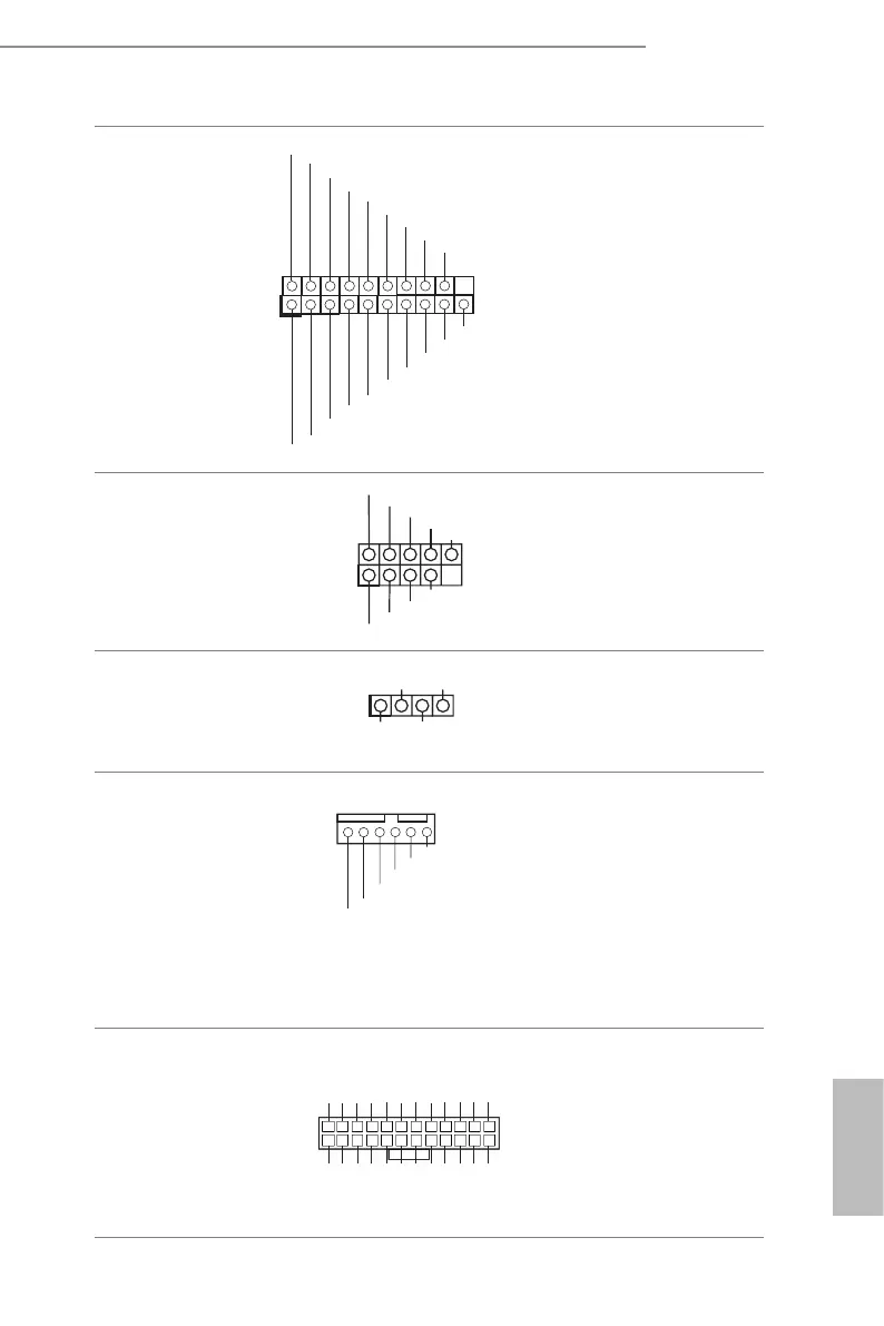
USB 3.2 Gen1 Header
(19-pin USB3_7_8)
Besides two default USB 3.2
Gen1 ports on the I/O panel,
there is one USB 3.2 Gen1
header on this motherboard.
is USB 3.2 Gen1 header can
support two USB 3.2 Gen1
ports.
USB 2.0 Header
(9-pin USB_1_2)
DUMMY
GND
GND
+B
-B
USB_PWR
+A
-A
1
ere is one USB 2.0 header on
this motherboard. Each USB
2.0 header can support two
ports.
Chassis Speaker Header
(4-pin SPEAKER1)
1
+5V
DUMMY
DUMMY
SPEAKER
Please connect the chassis
speaker to this header.
System Fan Connectors
(6-pin FAN1)
(6-pin FAN2)
(6-pin FAN3)
(6-pin FAN4)
(6-pin FAN5)
(6-pin FAN6)
(6-pin FAN7)
FAN_SPEED_SENSOR1
FAN_SPEED_CONTROL
FAN_VOLTAGE
GND
FAN_SPEED_SENSOR2
Please connect fan cables to the
fan connectors and match the
black wire to the ground pin.
All fans support Fan Control.
ATX Power Connector
(24-pin ATXPWR1)
3V
3V
GND
GND
5V
5V
GND
5VSB
12V
12V
3V
121
13
24
3V
-12V
GND
PSON#
GND
GND
GND
5V
5V
5V
GND
N/A
is motherboard provides a
24-pin ATX power connector.
To use a 20-pin ATX power
supply, please plug it along Pin
1 and Pin 13.
1
GND
GND
Vbus
GND
GND
IntA_PA_SSRX+
Vbus
IntA_PA_D-
IntA_PA_SSTX+
IntA_PA_SSTX-
IntA_PA_SSRX-
IntA_PB_SSRX-
IntA_PB_SSRX+
IntA_PB_SSTX-
IntA_PBA_SSTX+
IntA_PB_D-
IntA_PB_D+
 Loading...