34
2.8 Onboard Headers and Connectors
Onboard headers and connectors are NOT jumpers. Do NOT
place jumper caps over these headers and connectors. Plac-
ing jumper caps over the headers and connectors will cause
permanent damage to the motherboard!
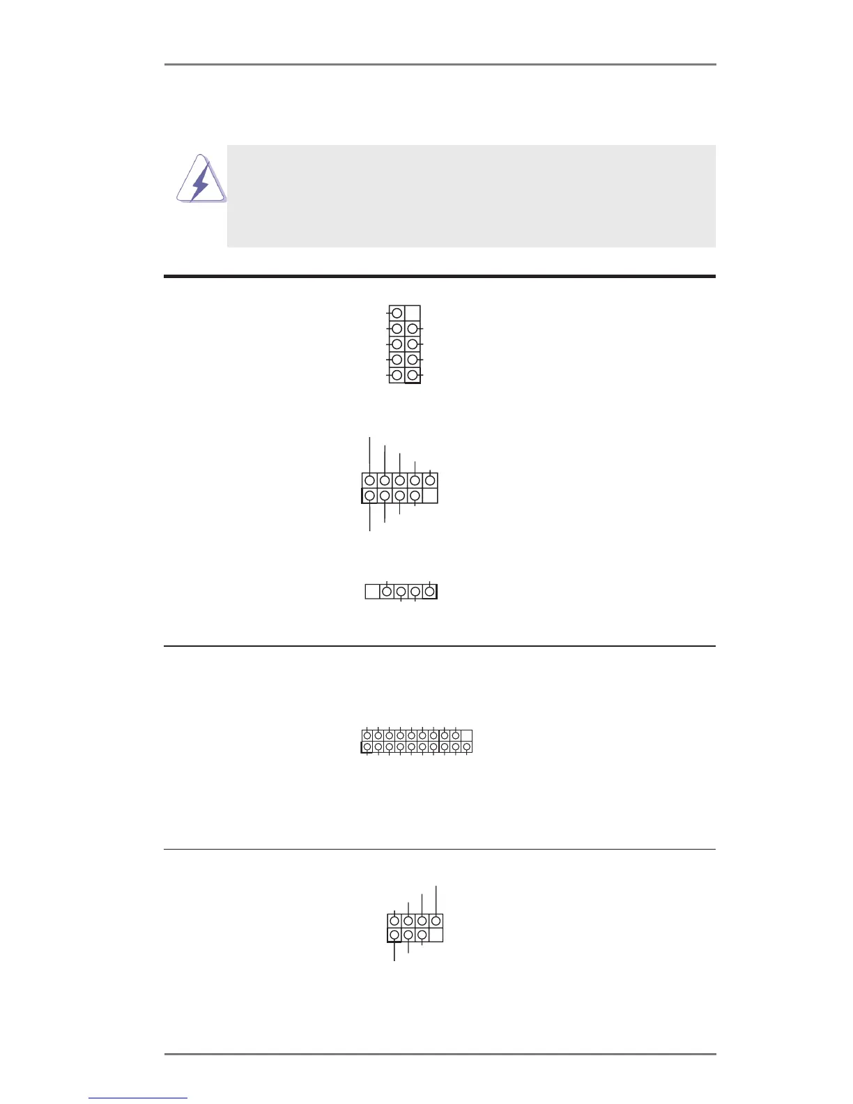
USB 2.0 Headers
(9-pin USB4_5)
(see p.13/15/17/19, No. 20)
(9-pin USB6_7)
(see p.13/15/17/19, No. 7)
(4-pin USB8)
(see p.13/15/17/19, No. 3)
Besides two default USB 2.0
ports on the I/O panel, there
are three USB 2.0 headers
and one USB port on this
motherboard. Each USB
2.0 header can support two
USB 2.0 ports.
DUMMY
GND
GND
+B
-B
USB_PWR
+A
-A
USB_PWR
1
USB 3.0 Header
(19-pin USB3_0_1)
(see p.13/15/17/19, No. 9)
Besides two default USB 3.0
ports on the I/O panel, there
is one USB 3.0 header on
this motherboard. The USB
3.0 header can support two
USB 2.0 ports.
DUMMY
GND GND
+B
-B
+A
-A
USB_PWR
USB_PWR
1
+5VDC
+D -D
GND
1
1
I ntA_PB_D+
D ummy
I ntA_PB_D-
GND
I ntA_PB_SSTX+
GND
I ntA_PB_SSTX-
I ntA_PB_SSRX+
I ntA_PB_SSRX-
V bus
V bus
IntA_PA_SSRX-
IntA_PA_SSRX+
GND
IntA_PA_SSTX-
IntA_PA_SSTX+
GND
IntA_PA_D-
IntA_PA_D+
Consumer Infrared
Module Header
(7-pin CIR1)
(see p.13/15/17/19, No. 5)
This header can be used
t o c o n n e c t t h e r e m o t e
controller receiver.
1
GND
Learn-in
NC
+5VA
LED
+5VA
CIR input