EasyManuals Logo

ASROCK Fatal1ty X99X Killer Series Manual

ASROCK Fatal1ty X99X Killer Series
192 pages
To Next Page IconTo Next Page
To Previous Page IconTo Previous Page
Page #33 background imageLoading...
Page #33 background image
English
Fatal1ty X99X Killer Series
29
2.9 M.2_SSD (NGFF) Module Installation Guide
e M.2, also known as the Next Generation Form Factor (NGFF), is a small size and
versatile card edge connector that aims to replace mPCIe and mSATA. e Ultra M.2
Socket (M2) can accommodate either a M.2 SATA3 6.0 Gb/s module or a M.2 PCI Express
module up to Gen3 x4 (32 Gb/s). Please be noted that the Ultra M.2 Socket (M2) is shared
with the SSATA3_2 connector; you can only choose either the Ultra M.2 Socket (M2) or
the SSATA3_2 connector to use.
* If M.2 PCI Express module is installed, PCIE5 will be disabled.
Installing the M.2_SSD (NGFF) Module
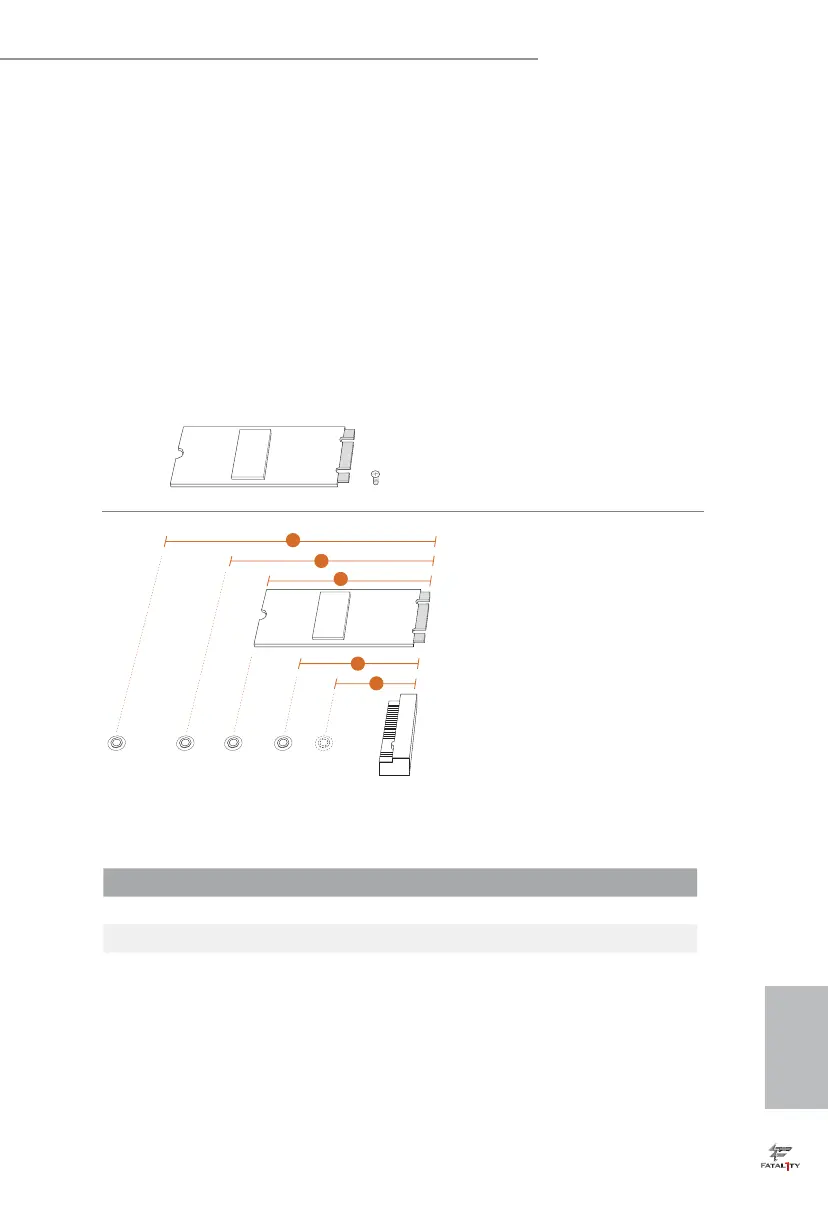
Step 1
Prepare a M.2_SSD (NGFF) module
and the screw.
3
2
4
5
BCDE
A
1
Step 2
Depending on the PCB type and
length of your M.2_SSD (NGFF)
module, nd the corresponding nut
location to be used.
No. 1 2 3 4 5
Nut Location A B C D E
PCB Length 3cm 4.2cm 6cm 8cm 11cm
Module Type Type2230 Type 2242 Type2260 Type 2280 Type 22110

Other manuals for ASROCK Fatal1ty X99X Killer Series

Questions and Answers:

Question and Answer IconNeed help?

Do you have a question about the ASROCK Fatal1ty X99X Killer Series and is the answer not in the manual?

ASROCK Fatal1ty X99X Killer Series Specifications

General IconGeneral
ChipsetIntel X99
CPU SocketLGA 2011-v3
Max Memory128GB
Form FactorATX
Memory Slots8 x DIMM
Expansion Slots3 x PCIe 3.0 x16, 2 x PCIe 2.0 x1
Multi-GPU SupportAMD 3-Way CrossFireX, NVIDIA Quad SLI
Storage Interface10 x SATA3
USB Ports4 x USB 3.0 ports (2 on the rear panel, 2 via header), 8 x USB 2.0 ports (4 on the rear panel, 4 via header)
AudioRealtek ALC1150 Audio Codec
LANKiller E2200 Series Gigabit LAN
Memory SupportDDR4 2800(OC)/2400(OC)/2133

Related product manuals