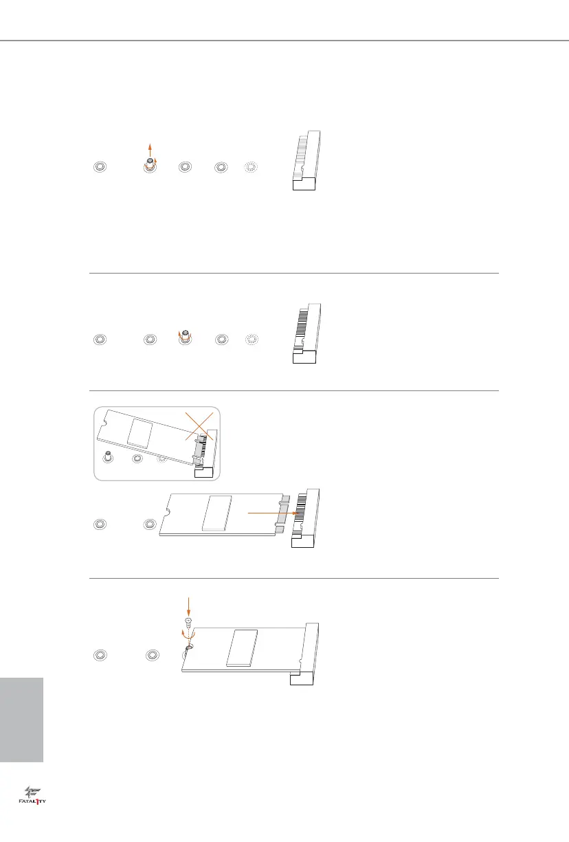
EasyManuals Logo

ASROCK Fatal1ty X99X Killer Series Manual

ASROCK Fatal1ty X99X Killer Series
192 pages
To Next Page IconTo Next Page
To Previous Page IconTo Previous Page
Page #34 background imageLoading...
Page #34 background image
English
30
BCDE
A
Step 3
Move the stando based on the
module type and length.
e stando is placed at the nut
location D by default. Skip Step 3
and 4 and go straight to Step 5 if you
are going to use the default nut.
Otherwise, release the stando by
hand.
BCDE
A
Step 4
Peel o the yellow protective lm on
the nut to be used. Hand tighten the
stando into the desired nut location
on the motherboard.
BC
A
ABCDE
Step 5
Align and gently insert the M.2
(NGFF) SSD module into the M.2
slot. Please be aware that the M.2
(NGFF) SSD module only ts in one
orientation.
NUT1NUT2DE
Step 6
Tighten the screw with a screwdriver
to secure the module into place.
Please do not overtighten the screw
as this might damage the module.

Other manuals for ASROCK Fatal1ty X99X Killer Series

Questions and Answers:

Question and Answer IconNeed help?

Do you have a question about the ASROCK Fatal1ty X99X Killer Series and is the answer not in the manual?

ASROCK Fatal1ty X99X Killer Series Specifications

General IconGeneral
ChipsetIntel X99
CPU SocketLGA 2011-v3
Max Memory128GB
Form FactorATX
Memory Slots8 x DIMM
Expansion Slots3 x PCIe 3.0 x16, 2 x PCIe 2.0 x1
Multi-GPU SupportAMD 3-Way CrossFireX, NVIDIA Quad SLI
Storage Interface10 x SATA3
USB Ports4 x USB 3.0 ports (2 on the rear panel, 2 via header), 8 x USB 2.0 ports (4 on the rear panel, 4 via header)
AudioRealtek ALC1150 Audio Codec
LANKiller E2200 Series Gigabit LAN
Memory SupportDDR4 2800(OC)/2400(OC)/2133

Related product manuals