12
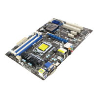
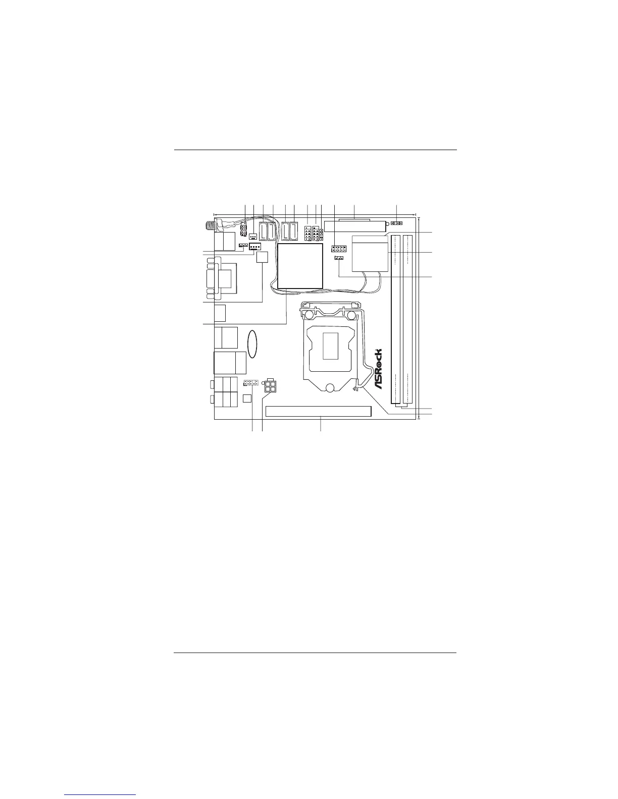
1.3 Motherboard Layout (H67M-ITX/HT)
1 System Panel Header (PANEL1, White) 14 WiFi-802.11n Module
2 Chassis Fan Connector (CHA_FAN1) 15 Clear CMOS Jumper (CLRCMOS1)
3 SATA3 Connector (SATA_0 (port 0), White) 16 2 x 240-pin DDR3 DIMM Slots
4 SATA3 Connector (SATA_1 (port 1), White) (Dual Channel: DDR3_A1, DDR3_B1, Blue)
5 SATA2 Connector (SATA_2 (port 4), Blue) 17 1155-Pin CPU Socket
6 SATA2 Connector (SATA_3 (port 5), Blue) 18 PCI Express 2.0 x16 Slot (PCIE1, Blue)
7 USB 2.0 Header (USB6_7, Blue) 19 ATX 12V Power Connector (ATX12V1)
8 USB 2.0 Header (USB8_9, Blue) 20 Front Panel Audio Header
9 Consumer Infrared Module Header (CIR1) (HD_AUDIO1, White)
10 COM Port Header (COM1) 21 Intel H67 Chipset
11 ATX Power Connector (ATXPWR1) 22 64Mb SPI Flash
12 Chassis Speaker Header (SPEAKER 1, White) 23 CPU Fan Connector (CPU_FAN1)
13 Mini PCI Express Slot (MINI_PCIE1) 24 Power LED Header (PLED1)
DDR3_A1 (64 bit, 240-pin module)
DDR3_B1 (64 bit, 240-pin module)
Intel
H67
ErP/EuP Ready
H67M-ITX/HT
PCIE1
AUDIO
CODEC
64Mb
BIOS
17.0cm (6.7 in)
17.0cm (6.7 in)
ATXPWR1
ATX12V1
CMOS
Battery
MINI_PCIE1
USB6_7
1
1
USB8_9
SATA_2 (port 4)
SATA_3 (port 5)
SATA_0 (port 0)
SATA_1
(port 1)
HDLED RESET
PLED PWRBTN
PANE L1
CLRCMOS1
1
1
PLED1
1
1
SPEAKER1
CIR1
1
CHA_FAN1
CPU_FAN1
COM1
1
1
HD_AUDIO1
Top:
CTR BASS
Center:
REAR SPK
Bottom:
Optical
SPDIF
Top:
LINE IN
Center:
FRONT
Bottom:
MIC IN
Top:
RJ-45
USB 3.0
T: U SB 4
B: USB5
ESATA1
USB 2.0
T: USB2
B: USB3
VGA1
DVI_CON1
HDMI1
USB 2.0
T: U S B0
B: USB1
PS2
Keyboard
RoHS
WiFi-802.11n
Module
1
2
3
4
5
6
11
12
13
14
10
7
8
9
16
15
17
18
24
19
20
21
22
23
 Loading...