20
English
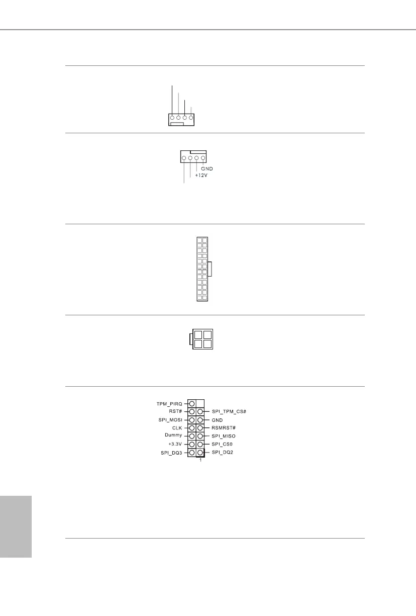
Chassis Fan Connector
(4-pin CHA_FAN1)
(see p.1, No. 12)
Please connect fan cables
to the fan connectors and
match the black wire to
the ground pin.
CPU Fan Connector
(4-pin CPU_FAN1)
(see p.1, No. 1)
is motherboard pro-
vides a 4-Pin CPU fan
(Quiet Fan) connector.
If you plan to connect a
3-Pin CPU fan, please
connect it to Pin 1-3.
ATX Power Connector
(24-pin ATXPWR1)
(see p.1, No. 3)
is motherboard pro-
vides a 24-pin ATX power
connector. To use a 20-pin
ATX power supply, please
plug it along Pin 1 and Pin
13.
ATX 12V Power
Connector
(4-pin ATX12V1)
(see p.1, No. 17)
is motherboard
provides an 4-pin ATX
12V power connector.
SPI TPM Header
(13-pin SPI_TPM_J1)
(see p.1, No. 14)
is connector supports
SPI Trusted Platform
Module (TPM) system,
which can securely store
keys, digital certicates,
passwords, and data. A
TPM system also helps
enhance network security,
protects digital identities,
and ensures platform
integrity.
+12V
CHA_FAN_SPEED
FA N_SPEED_CONTRO L
12
1
24
13
CPU_FAN _SPEE D
FAN_SPE ED_CO NTROL
4 3 2 1
 Loading...