1010
1010
10
1.3 Motherboard Layout1.3 Motherboard Layout
1.3 Motherboard Layout1.3 Motherboard Layout
1.3 Motherboard Layout
Super
I/O
CMOS
BATTERY
ATXPWR1
SOCKET AM3
CD1
NVIDIA
nForce 720D
Chipset
PS2_USB_PW1
1
IDE1
FSB800
DDR3_A1 (64 bit, 240-pin module)
DDR3_B1 (64 bit, 240-pin module)
FSB800
DDR3_A2 (64 bit, 240-pin module)
DDR3_B2 (64 bit, 240-pin module)
PCI1
AUDIO
CODEC
1
CLRCMOS1
CPU_FAN1
HDLED RESET
PLED PWRBTN
1
PANEL1
PWR_FAN1
SPEAKER1
1
FLOPPY1
HD_AUDIO1
1
RoHS
30.5cm (12.0-in)
19.1cm (7.5-in)
6
7
1
2
4
3
5
8
9
10
11
12
13
14
15
16
17
181920
21
22
23
24
25
26
27
28
PCIE1
1
HDMI_SPDIF1
29
8Mb
BIOS
SATAII_1(PORT 0)
HT3.0
Phenom II
DDR3 1800
PCI Express 2.0
PCI2
USB8_9
1
30
31
32
33
PCI3
M3N78D
COM1
1
34
LAN
PHY
Top:
SIDE SPK
Center:
REAR SPK
Bottom:
CTR BASS
Top:
LINE IN
Center:
FRONT
Bottom:
MIC IN
PS2
Mouse
PS2
Keyboard
USB 2.0
T: U SB 0
B: USB1
Top:
RJ-45
Coaxial
SPDIF
Optical
SPDIF
USB 2.0
T: U SB 4
B: USB5
USB10_11
1
USB6_7
1
SATAII_2(PORT 1)
SATAII_3(PORT 2)
SATAII_4(PORT 3)
CHA_FAN1
PCIE2
PCIE3
PCIE4
Dual Channel
eSATAII6/USB3
eSATAII5/USB2
ATX12V1
AM3
140W CPU
FSB2.6GHz
PLED1
1
CI1
1
35
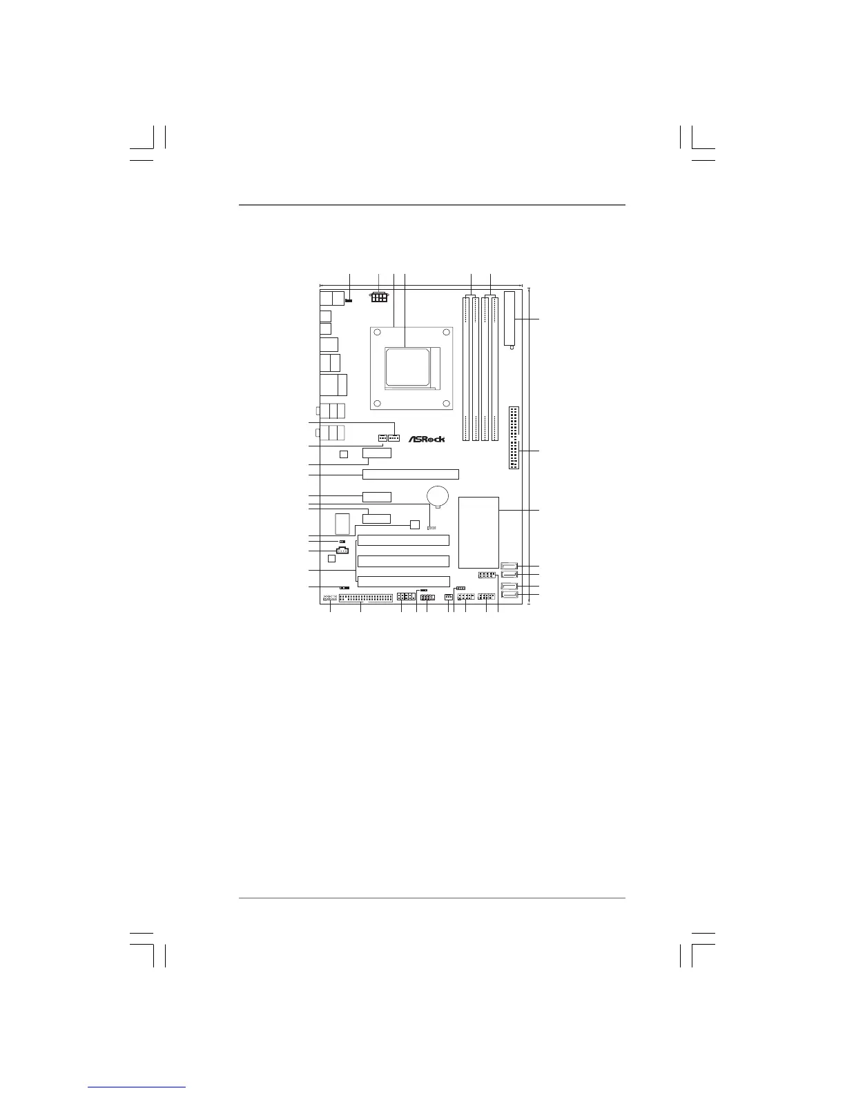
1 PS2_USB_PW1 Jumper 19 System Panel Header (PANEL1, Orange)
2 ATX 12V Power Connector (ATX12V1) 20 Power LED Header (PLED1)
3 CPU Heatsink Retention Module 21 Serial Port Connector (COM1)
4 AM3 CPU Socket 22 Floppy Connector (FLOPPY1)
5 2 x 240-pin DDR3 DIMM Slots 23 Front Panel Audio Header
(Dual Channel A: DDR3_A1, DDR3_B1; Blue) (HD_AUDIO1, Lime)
6 2 x 240-pin DDR3 DIMM Slots 24 HDMI_SPDIF Header
(Dual Channel B: DDR3_A2, DDR3_B2; White) (HDMI_SPDIF1, Yellow)
7 ATX Power Connector (ATXPWR1) 25 PCI Slots (PCI1- 3)
8 Primary IDE Connector (IDE1, Blue) 26 Internal Audio Connector: CD1 (Black)
9 NVIDIA nForce 720D Chipset 27 Chassis Intrusion Header (CI1)
10 SATAII Connector (SATAII_4 (PORT 3), Red) 28 SPI BIOS Chip
11 SATAII Connector (SATAII_3 (PORT 2), Red) 29 PCI Express x1 Slot (PCIE4, White)
12 SATAII Connector (SATAII_2 (PORT 1), Red) 30 Clear CMOS Jumper (CLRCMOS1)
13 SATAII Connector (SATAII_1 (PORT 0), Red) 31 PCI Express x1 Slot (PCIE3, White)
14 USB 2.0 Header (USB6_7, Blue) 32 PCI Express x16 Slot (PCIE2, Blue)
15 USB 2.0 Header (USB10_11, Blue) 33 PCI Express x1 Slot (PCIE1, White)
16 USB 2.0 Header (USB8_9, Blue) 34 Chassis Fan Connector (CHA_FAN1)
17 Chassis Speaker Header (SPEAKER 1, Purple) 35 CPU Fan Connector (CPU_FAN1)
18 Power Fan Connector (PWR_FAN1)
 Loading...