2121
2121
21
A. Connect Mic_IN (MIC) to MIC2_L.
B. Connect Audio_R (RIN) to OUT2_R and Audio_L (LIN) to OUT2_L.
C. Connect Ground (GND) to Ground (GND).
D. MIC_RET and OUT_RET are for HD audio panel only. You don’t
need to connect them for AC’97 audio panel.
E. Enter BIOS Setup Utility. Enter Advanced Settings, and then select
Chipset Configuration. Set the Front Panel Control option from
[Auto] to [Enabled].
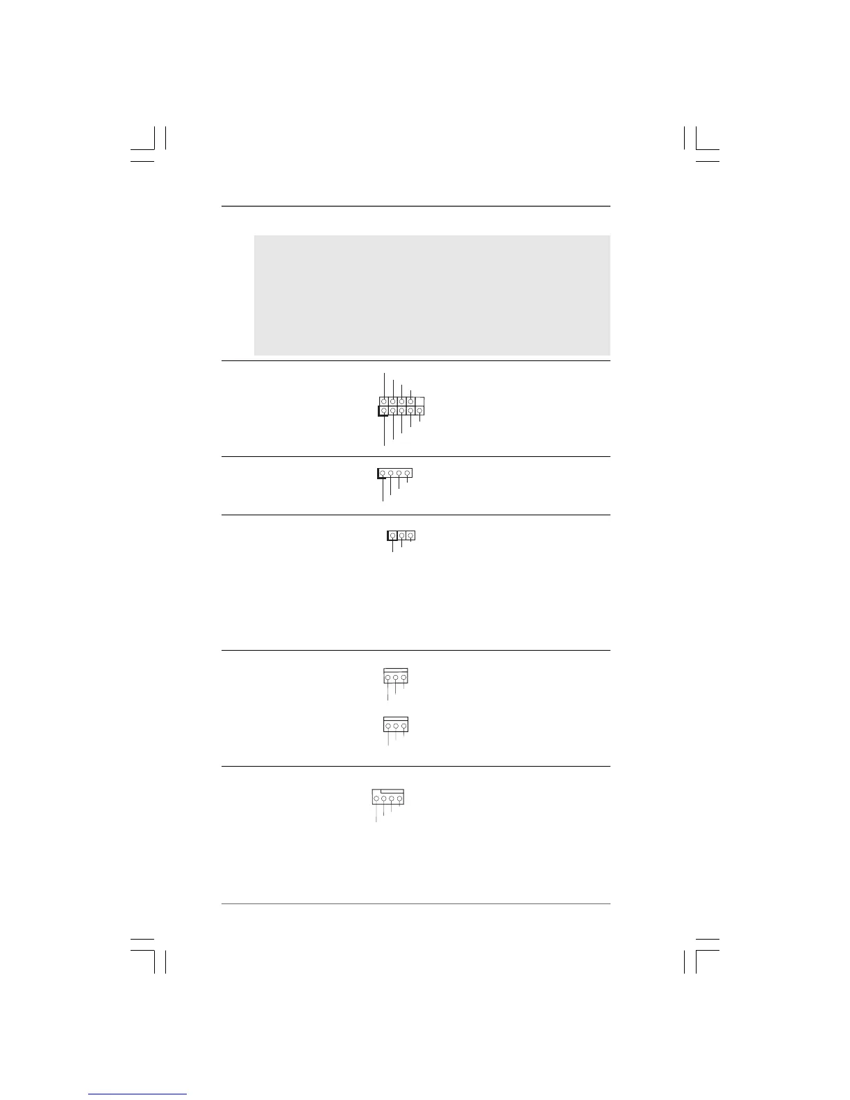
+5V
DUMMY
DUMMY
SPEAKER
1
GND
PWRBTN#
PLED-
PLED+
DUMMY
RESET#
GND
HDLED+
HDLED-
1
System Panel Header This header accommodates
(9-pin PANEL1) several system front panel
(see p.10, No. 19) functions.
Chassis Speaker Header Please connect the chassis
(4-pin SPEAKER 1) speaker to this header.
(see p.10, No. 17)
GND
+12V
CHA_FAN_SPEED
CPU Fan Connector Please connect the CPU fan
(4-pin CPU_FAN1) cable to this connector and
(see p.10, No. 35) match the black wire to the
ground pin.
GND
+12V
CPU_FAN_SPEED
FAN_SPEED_CONTROL
4 3 2 1
Chassis and NB Fan Connectors Please connect the fan cables
(3-pin CHA_FAN1) to the fan connectors and
(see p.10 No. 34) match the black wire to the
ground pin.
(3-pin PWR_FAN1)
(see p.10 No. 18)
GND
+12V
PWR_FAN_SPEED
Power LED Header Please connect the chassis
(3-pin PLED1) power LED to this header to
(see p.10 No. 20) indicate system power status.
The LED is on when the system
is operating. The LED keeps
blinking in S1 state. The LED is
off in S3/S4 state or S5 state
(power off).
1
PLED+
PLED+
PLED-
 Loading...