36
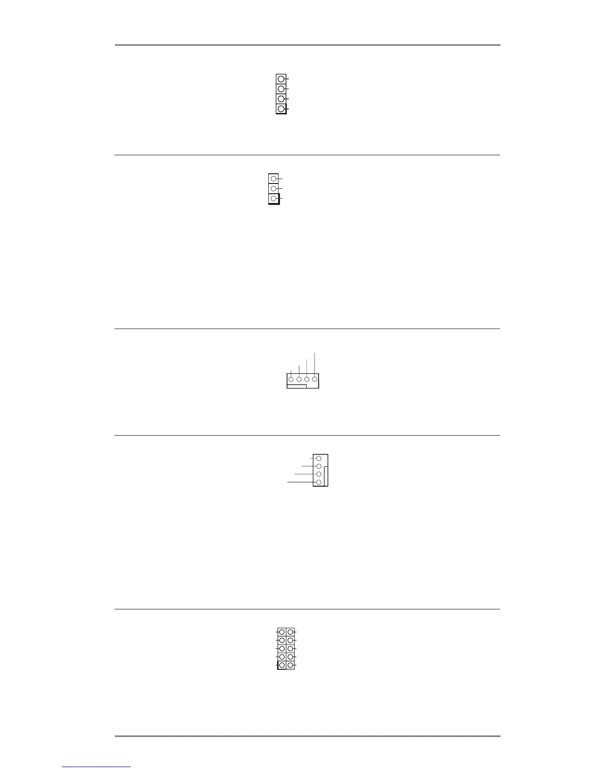
Power LED Header
(3-pin PLED1)
(see p.13/15/17/19, No. 11)
3W Audio AMP Output
Wafer Header
(4-pin SPEAKER1)
(see p.13/15/17/19, No. 28)
Please connect the chassis
speaker to this header.
Please connect the chassis
power LED to this header
to
indicate system power
status. The LED is on when
the system is operating. The
LED keeps blinking in S1/S3
state. The LED is off in S4
state or S5 state (power off).
Front_L+
Front_R-
1
Front_R+
Front_L-
PLED+
PLED+
PLED-
Chassis Fan Connector
(4-pin CHA_FAN1)
(see p.13/15/17/19, No. 4)
Please connect a fan cable
to the fan connector and
match the black wire to the
ground pin.
FAN_SPEED
FAN_SPEED_CONTROL
G ND
+12V
1 2 3 4
CPU Fan Connectors
(4-pin CPU_FAN1)
(see p.13/15/17/19, No. 22)
Though this motherboard
provides a 4-Pin CPU fan
(Quiet Fan) connector, 3-Pin
CPU fans can still work even
without fan speed control. If
you plan to connect a 3-Pin
CPU fan, please connect it
to Pin 1-3.
FAN_SPEED
FAN_SPEED_CONTROL
+12V
G ND
1
2
3
4
Serial Port Header
(10-pin COM1)
(see p.13/15/17/19, No. 18)
This COM1 header supports
a serial port module.
RXD
RTS
TXD
DTR
GND
CTS
COM PWR/RI
NC
1
DSR
COM PWR/DCD
 Loading...