782 Electric Latch
Retraction Controller
Installation Instructions
80-9477-0782-001 01/24
1-855-557-5078 • www.assaabloy.com
Copyright © 2014, 2023, 2024, ASSA ABLOY Access and Egress Hardware Group, Inc. All rights reserved. Reproduction in whole
or in part without the express written permission of ASSA ABLOY Access and Egress Hardware Group, Inc. is prohibited.
WARNING
This product can expose you to lead which is known to the state of California to cause cancer and birth defects or other
reproductive harm. For more information go to www.P65warnings.ca.gov.
WARNING
Attention Installer: Any retrot or other eld modication to a re rated opening can potentially impact the re rating of the opening,
and ASSA ABLOY makes no representations or warranties concerning what such impact may be in any specic situation. When
retrotting any portion of an existing re-rated opening, or specifying and installing a new re-rated opening, please consult with a
code specialist or local code ofcial (Authority Having Jurisdiction) to ensure compliance with all applicable codes and ratings.
The 782 is designed to be used with UL Listed 7000P series (electric latch retraction) or Corbin Russwin ED4000/ED5000 x M94
series (latch pullback) exit devices, and Corbin Russwin are ASSA ABLOY Group brands.
INSTALLATION
The 782 Electric Latch Retraction Controller shall be installed in accordance with the National Electricalm Code (ANSI/NFPA70), local
codes and the Authorities Having Jurisdiction (AHJ’s).
The 782 enclosure should be securely fastened to the wall using the four 1/4" diameter mounting holes located in the back of the
box. Position the enclosure so that the transformer is located on the left-hand side. The 782 is intended to be installed indoors
within the protected area only and wired to a 15 Ampere branch circuit. Install the enclosure to the mounting surface using suitable
hardware for the application. Anchors should be capable of holding a 20 lb static load.
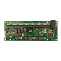
For the 120VAC power input, terminal block TB1 will accommodate up to 14 AWG wire. In order to provide an adequate earth
ground to the enclosure, the green grounding wire must be connected to earth ground with a wire connector as shown.
Note: The maximum input current is 750mA (10A inrush) @ 120VAC.
Use the chart below to determine the correct wire gauge per given length of two- conductor cable that will run from the 782 to each
exit device. Do not exceed the maximum length listed with each wire gauge.
EARTH (14 AWG)
GREEN wire (14 awg)
WIRE GAUGE
16 AWG
14 AWG
12 AWG
MAXIMUM LENGTH OF TWO-CONDUCTOR CABLE
40 FEET
60 FEET
100 FEET
Wire Connector
(Not included)
Circuit Board Standoff
Figure1
Table 1