782 Electric Latch
Retraction Controller
Installation Instructions
2
80-9477-0782-001 01/24
1-855-557-5078 • www.assaabloy.com
Copyright © 2014, 2023, 2024, ASSA ABLOY Access and Egress Hardware Group, Inc. All rights reserved. Reproduction in whole
or in part without the express written permission of ASSA ABLOY Access and Egress Hardware Group, Inc. is prohibited.
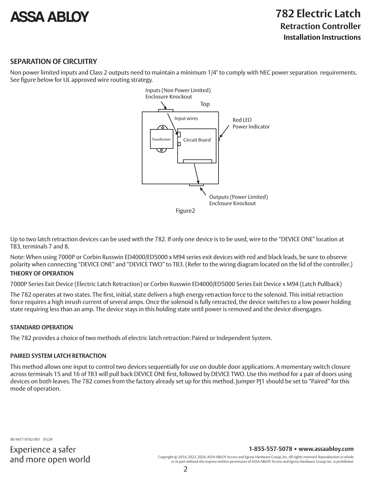
SEPARATION OF CIRCUITRY
Non power limited inputs and Class 2 outputs need to maintain a minimum 1/4" to comply with NEC power separation requirements.
See gure below for UL approved wire routing strategy.
Outputs (Power Limited)
Enclosure Knockout
Red LED
Power Indicator
Inputs (Non Power Limited)
Enclosure Knockout
Top
Circuit Board
Input wires
Transformer
Figure2
Up to two latch retraction devices can be used with the 782. If only one device is to be used, wire to the “DEVICE ONE” location at
TB3, terminals 7 and 8.
Note: When using 7000P or Corbin Russwin ED4000/ED5000 x M94 series exit devices with red and black leads, be sure to observe
polarity when connecting “DEVICE ONE” and “DEVICE TWO” to TB3. (Refer to the wiring diagram located on the lid of the controller.)
THEORY OF OPERATION
7000P Series Exit Device (Electric Latch Retraction) or Corbin Russwin ED4000/ED5000 Series Exit Device x M94 (Latch Pullback)
The 782 operates at two states. The rst, initial, state delivers a high energy retraction force to the solenoid. This initial retraction
force requires a high inrush current of several amps. Once the solenoid is fully retracted, the device switches to a low power holding
state requiring less than an amp. The device stays in this holding state until power is removed and the device disengages.
STANDARD OPERATION
The 782 provides a choice of two methods of electric latch retraction: Paired or Independent System.
PAIRED SYSTEM LATCH RETRACTION
This method allows one input to control two devices sequentially for use on double door applications. A momentary switch closure
across terminals 15 and 16 of TB3 will pull back DEVICE ONE rst, followed by DEVICE TWO. Use this method for a pair of doors using
devices on both leaves. The 782 comes from the factory already set up for this method. Jumper PJ1 should be set to “Paired” for this
mode of operation.