782 Electric Latch
Retraction Controller
Installation Instructions
4
80-9477-0782-001 01/24
1-855-557-5078 • www.assaabloy.com
Copyright © 2014, 2023, 2024, ASSA ABLOY Access and Egress Hardware Group, Inc. All rights reserved. Reproduction in whole
or in part without the express written permission of ASSA ABLOY Access and Egress Hardware Group, Inc. is prohibited.
AUXILIARY POWER SOURCE OUTPUT
A single unregulated/unltered constant DC power source is provided for powering keypads, motion sensors, annunciator panels,
electromagnetic door holders, relays, LEDs, etc. All interconnecting devices must be UL294 Listed.
Auxiliary Output: 24 VDC – 28 VDC Nominal, 250mA (Max.)
WARNING: THIS AUXILIARY POWER SOURCE CANNOT BE USED WITH EQUIPMENT REQUIRING A REGULATED OR FILTERED POWER
SOURCE. TO DO SO MAY CAUSE INADEQUATE OPERATION OF OR POSSIBLE DAMAGE TO THE EQUIPMENT. ALWAYS CHECK
THE MANUFACTURER’S SPECIFICATION FOR THE TYPE OF POWER SOURCE REQUIRED FOR THE EQUIPMENT TO BE USED
WITH THE 782.
NORMALLY OPEN RELAY CONTACTS
Normally open relay contacts (OPER 1 and OPER 2) are to be used as dry contact switch feedback to the host controller.
If PJ1 is set to paired use OPER 2 for feedback.
If PJ1 is set to single, use OPER 1 and OPER 2 for feedback of Dev 1 and Dev 2, respectively.
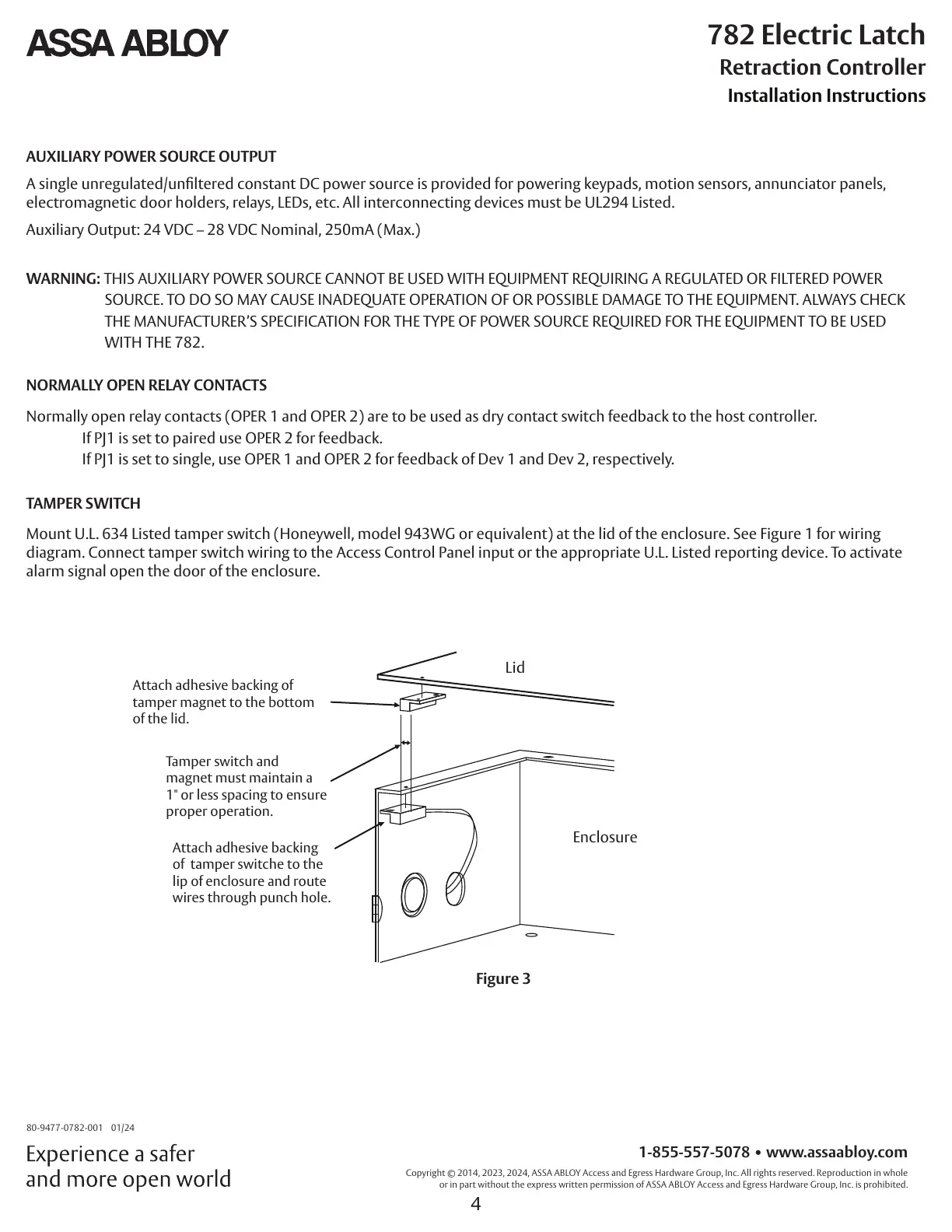
TAMPER SWITCH
Mount U.L. 634 Listed tamper switch (Honeywell, model 943WG or equivalent) at the lid of the enclosure. See Figure 1 for wiring
diagram. Connect tamper switch wiring to the Access Control Panel input or the appropriate U.L. Listed reporting device. To activate
alarm signal open the door of the enclosure.
Attach adhesive backing of
tamper magnet to the bottom
of the lid.
Tamper switch and
magnet must maintain a
1" or less spacing to ensure
proper operation.
Attach adhesive backing
of tamper switche to the
lip of enclosure and route
wires through punch hole.
Lid
Enclosure
Figure 3