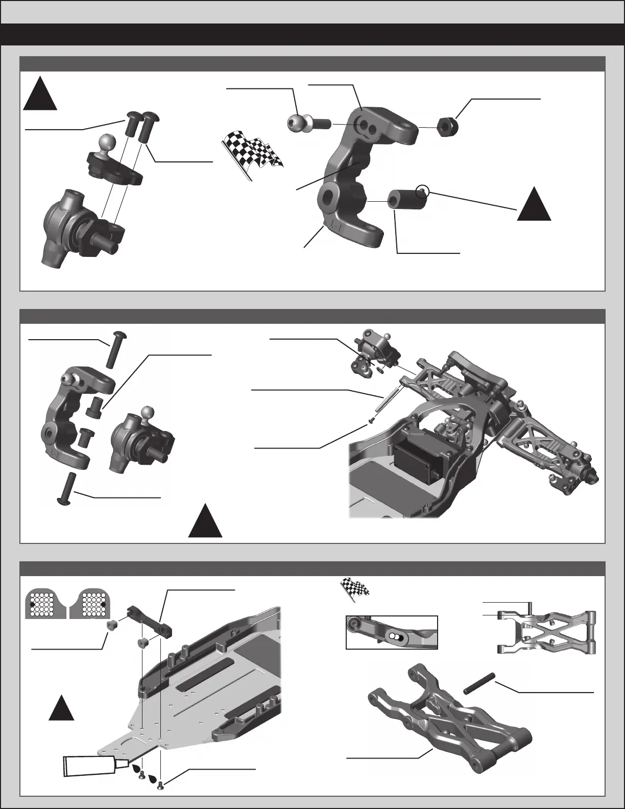
:: :: Bag 4 - Step 1Bag 4 - Step 1
:: :: Bag Bag 3 - Step 33 - Step 3
9
:: :: Bag 3 - Step 2Bag 3 - Step 2
Build 2 (1 left, 1 right)
91049
Heavy-duty
Ballstud,
10mm
25215
M3 Locknut,
black
91901
Caster
Block Insert
(+5°)
There are three caster
block inserts included
(0°, +/- 2.5 °, +/- 5 °).
+5 ° is the standard
insert used.
Tab up = positive caster
Tab down = negative caster
!
91901
Caster
Block
You can install an
optional #31520 screw
to use as a steering
stop setting.
You can install an
optional #4670 set
screw to better hold
the caster block inserts
and hinge pin.
31531
M3 x 6mm
BHCS
31532
M3 x 8mm
BHCS
Build 2 (1 left, 1 right) Build 2 (1 left, 1 right)
Build 2 (1 left, 1 right)
#91670 - Hinge Pin will be
tight in the caster blocks,
but should rotate freely
in the front arms.
Use shorter
screw in front!
!
!
25187
M3 x 14mm
BHCS
89202
M3 x 12mm
BHCS
91676
Caster Hat
Bushing
Top: 2mm
Bottom: 1mm
x2x2
31510
M2 x 4mm
BHCS
91776
Caster Block
Spacer
91670
Front Hinge Pin
(Outer, 3x26mm)
91853
B6.2 Rear
Arms, 73mm
x2x2
x2x2
91737
M3 x 20mm
Set Screw
You can use a dot of CA glue to better secure
the lower shock mounting set screw
11mm
See next
step for pill
chart tips
!
Arm Mount C: 1° Out
91882
Aluminum
Arm Mount, C
92014
Arm Mount
Inserts
(1°)
x2x2
31541
M3 x 6mm
FHCS
x2x2
#1596
thread lock
BC
A