:: Bag 4 - Step 1
:: Bag 3 - Step 3
9
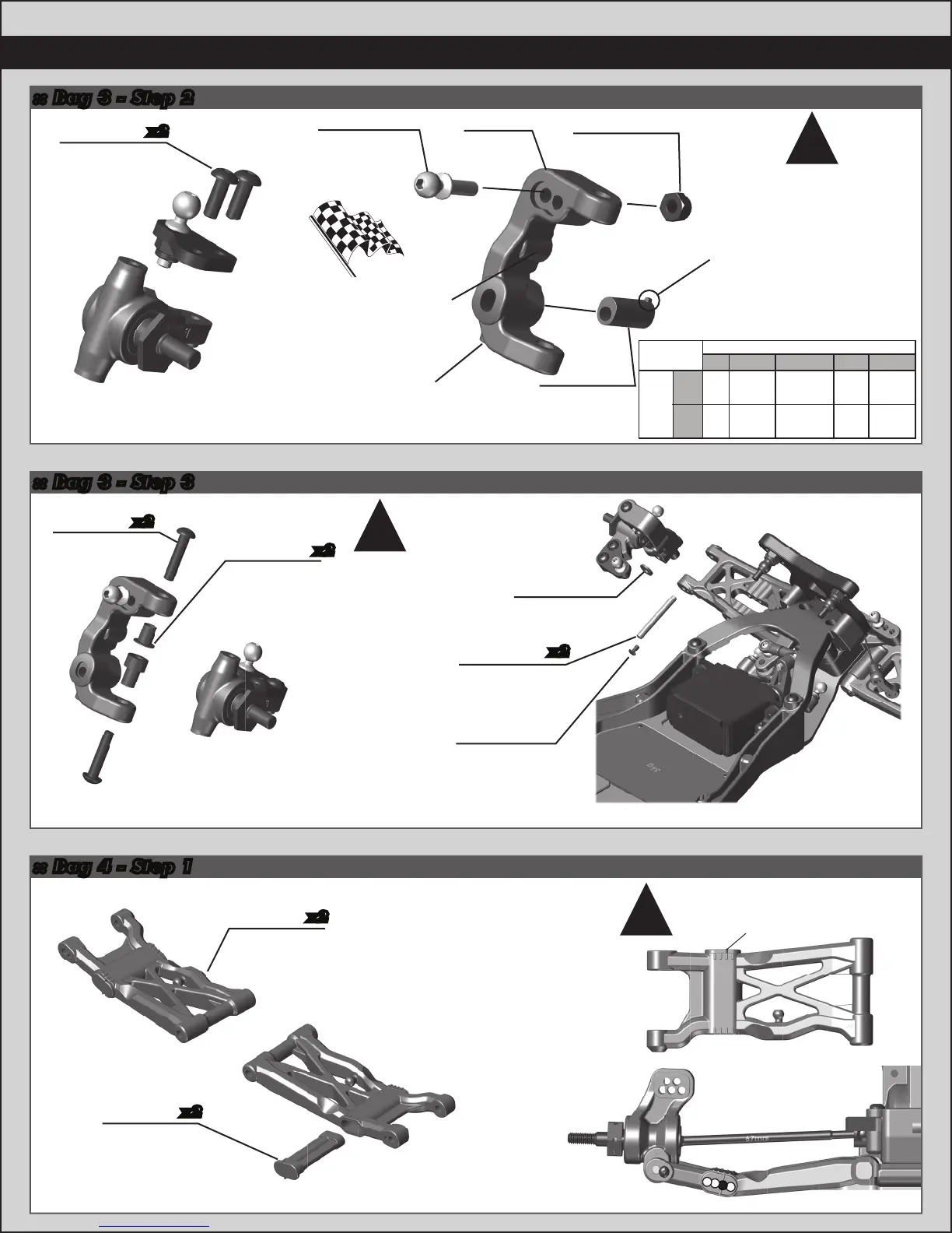
:: Bag 3 - Step 2
Build 2 (1 left, 1 right)
31532
M3 x 8mm
BHCS
x2
Build 2 (1 left, 1 right) Build 2 (1 left, 1 right)
31510
M2 x 4mm
BHCS
91675
Caster Block
Spacer
91670
Hinge Pin
(front, Outer)
x2
91049
Heavy-duty
Ballstud,
10mm
25215
M3 Locknut,
black
91675
Caster
Block Insert
(+5°)
There are three caster
block inserts included
(0°, +/- 2.5 °, +/- 5 °).
+5 ° is the standard
insert used.
Tab up = positive caster
Tab down = negative caster
!
91675
Caster
Block
You can install an
optional #31520 screw
to use as a steering
stop setting.
You can install an
optional #4670 set
screw to better hold
the caster block inserts
and hinge pin.
Total
Caster
25° 25° 30° 20°2 7. 5 ° 22.5°
0 2.5 up 5 up2.5 down 5 down
30° 30° 35° 25°32.5° 2 7. 5 °
Bulkhead
Orientation
Caster Block Insert
x2
25187
M3 x 14mm
BHCS
91676
Caster Hat
Bushing
Top: 0mm
Bottom: 3mm
x2
91777
Rear
Arms (L&R)
91777
Rear Arm
Threaded
Insert
x2
x2
BCD
A
Install the rear arm threaded
insert in the same position for
the left and right side arms!
#91670 - Hinge Pin will be
tight in the caster blocks,
but should rotate freely
in the front arms.
!
!
 Loading...